Dry ash sealing and telescopic bulk device

A bulk device, dry ash technology, applied in transportation and packaging, loading/unloading, dispersed particle filtration, etc., can solve the problems of dry ash reducing work efficiency, secondary waste, low filling efficiency, and large amount of dry ash escaping.

Pending Publication Date: 2021-08-20
中电国瑞供应链管理有限公司淮南分公司
View PDF0 Cites 2 Cited by
  • Summary
  • Abstract
  • Description
  • Claims
  • Application Information

AI Technical Summary

Problems solved by technology

[0002] At present, the bulk device for dry ash is mainly composed of a feeding pipe, a vacuum pipe and a dry ash transport vehicle box. The dry ash enters through the inner pipe. Due to the existence of gaps between the folded cone pipes, the dry ash flows during the descent process. Being sucked in by the dust

Method used


Image

  • Dry ash sealing and telescopic bulk device
  • Dry ash sealing and telescopic bulk device
  • Dry ash sealing and telescopic bulk device

Examples


Embodiment 1

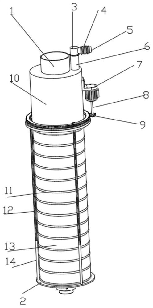
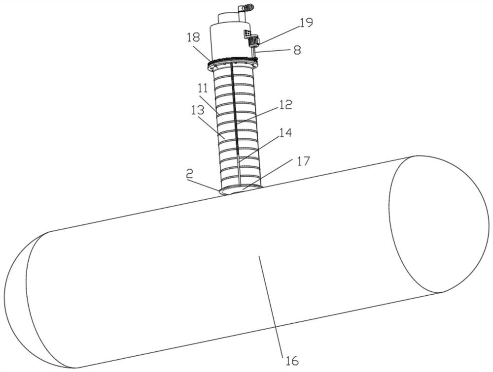
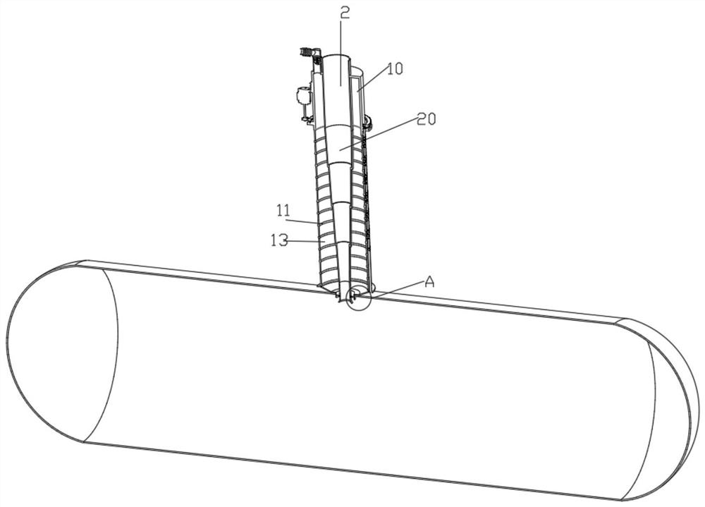
[0034] Such as figure 1 , 2, shown in 3, 4, 5, 9, a kind of dry ash sealing shrinkage bulk device, comprises feeding pipe 1 and tank car 16, and the top middle end of tank car 16 is provided with feeding hole 161, and the bottom of feeding pipe 1 is provided with There are shrink sleeves 20, and there are six groups of shrink sleeves 20, the bottom of the inner wall of the upper set of shrink sleeves 20 is in contact with the top outer wall of the next set of shrink sleeves 20, and the uppermost shrink sleeve 20 The top is fixedly connected with the top of the feeding pipe 1, and the shrink sleeve 20 is inclined inwardly by 2° in the vertical direction, and the bottom of the lowermost shrink sleeve 20 is fixedly connected with a blanking inner ring 28, and the feeding pipe The outer wall of the upper end of 1 is fixedly connected with a dust suction sleeve 10, and the top of the dust suction sleeve 10 is fixedly connected with a straight pipe 6, and the straight pipe 6 is con...

Embodiment 2

[0037] Embodiment 2 is a further improvement to Embodiment 1.

[0038] Such as figure 1 , 2 , 3, 4, 5, 7, and 8, the height adjustment structure includes a support ring 2, a first rotating shaft 8, a ring gear 9, a connecting pipe 11, a thread groove 12, a dustproof canvas 13, a straight rod 14, Connecting sleeve 18, drive motor 19, lower flange 21, first threaded sleeve 22, first bearing 23, upper flange 29, gear block 30 and support ring 31, upper flange 29 is fixedly installed on the bottom of dust suction casing 10 The bottom of the outer wall, the top of the connecting sleeve 18 is fixedly connected with the lower flange 21, the upper flange 29 and the lower flange 21 are connected by bolts, the top of the first threaded sleeve 22 is fixedly connected with the first bearing 23, and the inner part of the first bearing 23 The top of the ring is fixedly connected with a support ring 31, the top of the support ring 31 is fixedly connected with a first threaded sleeve 22, th...

Embodiment 3

[0040] Embodiment 3 is a further improvement to Embodiment 1.

[0041] Such as Figure 6 As shown, the connection structure includes a second threaded sleeve 24, a bolt 25 and a groove 26. The second threaded sleeve 24 is evenly fixed and installed on the outer wall of the blanking inner ring 28 along the circumferential direction, and the groove 26 is evenly opened on the lower wall along the circumferential direction. The outer wall of the outer ring 27 of the feed port, the outer ring 27 of the feed port is rotatably connected with a groove 26, and the inner end of the groove 26 is threadedly connected with the second threaded sleeve 24, and the second threaded sleeve 24 and the bolt 25 of the connecting structure Used together, the inner ring 28 of the blanking is limited in the outer ring 27 of the blanking port, which ensures the normal ventilation of the outer ring 27 of the blanking port and the inner ring 28 of the blanking port, and prevents the inner ring 28 of the ...


PUM


Abstract

The invention discloses a dry ash sealing telescopic bulk device, and relates to the technical field of dry ash conveying. The dry ash sealing telescopic bulk device comprises a discharging pipe and a tank car, wherein a feeding hole is formed in the middle end of the top of the tank car, six groups of telescopic sleeves are arranged at the bottom of the discharging pipe, the bottoms of the inner walls of the upper group of telescopic sleeves make contact with the outer walls of the tops of the lower group of telescopic sleeves in an attached mode, the bottom of the telescopic sleeve at the lowest end is fixedly connected to a discharging inner ring, the outer wall of the upper end of the discharging pipe is fixedly connected to a dust collection sleeve, the top of the dust collection sleeve is fixedly connected to a straight pipe, the straight pipe is connected to a filtering structure used for filtering dust, the filtering structure has a blockage clearing function, the top of the straight pipe is in threaded connection with the straight pipe, and the side wall of the straight pipe is fixedly connected to a supporting ring. According to the above solution, no gap exists after each stage of telescopic sleeves is expanded, so that dry ash does not escape due to the existence of pressure difference in the falling process of the discharging pipe.

Description

technical field [0001] The invention relates to the technical field of dry ash transportation, in particular to a dry ash sealing and shrinking bulk device. Background technique [0002] At present, the bulk device for dry ash is mainly composed of a discharge pipe, a vacuum pipe and a dry ash transport vehicle box. The dry ash enters through the inner pipe. Due to the existence of gaps between the folded cone pipes, the dry ash flows during the descent process. Being sucked in by the dust suction fan, the dry ash cannot completely fall into the tank car box, thereby reducing work efficiency and secondary waste. There is a large amount of dry ash escaping between the inner and outer pipelines, and there are dry ash being sucked back and Dust is emitted, resulting in low filling efficiency. [0003] Therefore, in order to improve work efficiency and prevent dry ash from being sucked back and blown out, it is necessary to design a dry ash sealing and shrinking bulk device to ...

Claims


Application Information

Patent Timeline
IPC IPC(8): B65G67/06B65G69/00B65G69/18B01D46/42B01D46/00
CPCB65G67/06B65G69/00B65G69/182B01D46/42B01D46/681
Inventor 来永斌毕波刘世情
Owner 中电国瑞供应链管理有限公司淮南分公司
Why Eureka
Try Eureka