RCLED lamp bead packaging process

A packaging process and lamp bead technology, which is applied in the direction of electrical components, circuits, semiconductor devices, etc., can solve the problems of inability to eliminate the reflection effect, affect the overall effect of the light spot, and the influence of the light spot, and achieve slow flow, small thickness, and reduced The effect of dispensing volume

Active Publication Date: 2021-08-20
PSG OPTO DEV CO LTD
View PDF10 Cites 2 Cited by
  • Summary
  • Abstract
  • Description
  • Claims
  • Application Information

AI Technical Summary

Problems solved by technology

However, when the light emitted by the RCLED passes through the lens, part of the light will be reflected by the lens, and the light spot reflected by the lens will be reflected again by the functional area and bonding wire in the RCLED lamp bead, which will affect the emitted RCLED light spot. Causes impact, forming spots or ghosting, seriously affecting the overall effect of the spot
[0004] The traditional LED lamp bead packaging process cannot eliminate the above-mentioned reflection effect

Method used


Image

  • RCLED lamp bead packaging process
  • RCLED lamp bead packaging process

Examples


Embodiment Construction

[0036] In order to make the technical means, creative features, goals and effects achieved by the present invention easy to understand, the present invention will be further described below in conjunction with specific embodiments.

[0037] It should be noted that the terms "first", "second" and similar expressions used herein are for the purpose of illustration only, and do not represent the only implementation manner.

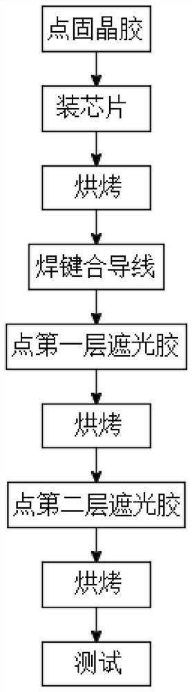
[0038] An RCLED lamp bead packaging process, the process specifically includes the following steps:

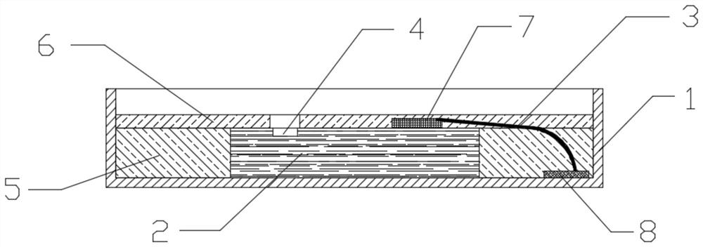
[0039] Step 1, apply the crystal-bonding glue, put the crystal-bonding glue into the designated position of the lamp bead bracket (1), and the lamp bead bracket (1) includes the lead frame (8);

[0040] Step 2, install the chip, put the RCLED chip (2) into the glue dispensing area of ​​the lamp bead bracket, the RCLED chip (2) includes the light-emitting hole (4), PAD (7);

[0041] Step 3, baking to solidify the crystal-bonding glue, the crystal-bonding glue...


PUM


Abstract

The invention discloses an RCLED lamp bead packaging process, which comprises the following steps of dispensing solid crystal glue, mounting a chip, baking, welding a bonding wire, dispensing a first layer of anti-reflection glue, baking, dispensing a second layer of anti-reflection glue, baking and testing. The anti-reflection glue is dispensed in a corresponding area of an RCLED lamp bead, so that a part capable of reflecting light in the RCLED lamp bead is shielded; the reflection effect of the RCLED lamp bead is effectively eliminated, the light spot emitting effect of the RCLED lamp bead is improved, and the light spots are clearer and more accurate. And the viscosity of the first layer of anti-reflection glue has certain flowability, so that the anti-reflection glue can be rapidly filled in a specified area, and the production efficiency is high. And the second layer of anti-reflection glue is relatively high in viscosity and flows slowly after glue dispensing, so that the glue dispensing precision is improved, and the anti-reflection glue can be effectively prevented from shielding a light-emitting hole of the RCLED chip. When the bonding wire is welded, the support is the first welding spot, and the PAD of the RCLED chip is the second welding spot, so that the radian of the bonding wire is lower, the lamp bead has a good appearance, the dispensing amount is reduced, and the production cost is saved.

Description

technical field [0001] The invention relates to the technical field of lamp bead packaging, in particular to an RCLED lamp bead packaging process. Background technique [0002] RCLED, namely Resonant Cavity Light Emitting Diode, the English full name is "Resonant Cavity Light Emitting Diode", is a new type of light emitting diode structure, which has the advantages of both traditional LED and vertical cavity surface laser (VCSEL), through its microcavity effect The function changes the mode of spontaneous emission in the active region, and then limits the frequency and angle of the radiation spectrum, which can greatly improve the internal and external quantum efficiency. It is a very excellent structure for preparing high-brightness LEDs. [0003] Due to the advantages of RCLEDs, RCLEDs are usually used as emission light sources in fields such as sights. But when the light emitted by the RCLED passes through the lens, part of the light will be reflected by the lens, and th...

Claims


Application Information

Patent Timeline
Patent Type & Authority Applications(China)
IPC IPC(8): H01L33/00H01L33/44H01L33/52H01L33/62
CPCH01L33/005H01L33/44H01L33/52H01L33/62H01L2933/0025H01L2933/005H01L2933/0066H01L33/105H01L33/486H01L33/56G02B1/11F21Y2115/10F21K9/60F21K9/90F21V19/0025F21V23/002
Inventor 苏三
Owner PSG OPTO DEV CO LTD
Why Eureka
Try Eureka