Working platform for architectural design

A technology of working platform and architectural design, which is applied to the table or table of computer workstation, the legs of general furniture, the combination of two or more pieces of different kinds of furniture, etc. Putting computer tools and hand-painting tools and other issues to achieve the effect of increasing the top area and facilitating adjustment

Active Publication Date: 2021-08-24
梁晨
View PDF11 Cites 0 Cited by
  • Summary
  • Abstract
  • Description
  • Claims
  • Application Information

AI Technical Summary

Problems solved by technology

[0005] In order to solve the above-mentioned technical problems, the present invention provides a working platform for architectural design, to solve the problem that when the existing working platform for architectural design is in use, the entire desktop needs to be tilted as a whole to make it stand on the table. There is nowhere to place the original materials, so that the desktop needs to be cleaned in advance before the exhibition, and when the existing architectural design work platform is in use, due to the limited desktop area, it is impossible to place computer tools and hand-painted tools at the same time. There is also a problem with limiting the number of users

Method used


Image

  • Working platform for architectural design
  • Working platform for architectural design
  • Working platform for architectural design

Examples


Embodiment

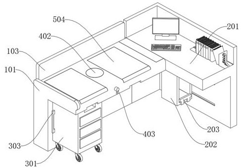
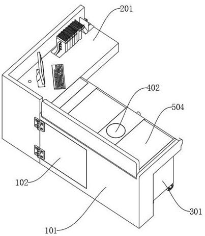
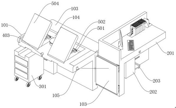
[0061] as attached figure 1 to attach Figure 9 Shown:

[0062] The present invention provides a working platform for architectural design, which includes a support mechanism 1; The L-shaped block on the side, and the rotating part 201 of the rotating mechanism 2 is put into the rear side and connected with the rear sliding plate 102 through a hinge; the auxiliary mechanism 3 is arranged on the left bottom of the supporting mechanism 1, and the auxiliary mechanism 3 The rear side U-shaped protrusion of the loading box 301 is inserted into the rectangular groove on the front side of the main body 101; wherein, the auxiliary mechanism 3 includes: the loading box 301, the loading box 301 is a cuboid structure, and the front side of the loading box 301 is provided with a rectangular groove, and the rear side of the loading box 301 is provided with a rectangular groove, the bottom of the loading box 301 is provided with universal wheels, and the rear side of the loading box 301 i...


PUM


Abstract

The invention provides a working platform for architectural design, relates to the technical field of design platforms, and aims to solve the problem that a computer tool and a hand drawing tool cannot be simultaneously placed on an existing working platform for architectural design due to limited desktop area when the working platform for architectural design is used. The working platform includes a supporting mechanism; a rotating mechanism is arranged on the right side of the supporting mechanism; the auxiliary mechanism is arranged at the left bottom of the supporting mechanism; the lifting mechanism is arranged in the middle of the supporting mechanism; and the turnover mechanism is arranged at the top of the supporting mechanism. The supporting mechanism and the rotating mechanism are arranged, the supporting mechanism is mostly used for hand drawing design, the rotating mechanism is used for computer design, the rotating piece is connected to the rear sliding plate through the hinge, the rotating mechanism can rotate around the supporting mechanism through the hinge, and by rotating the top plate, the top area of the main body is increased, so that use of the working platform by multiple persons is facilitated; and by adjusting the rotating piece, the hand drawing area of the device is separated from the computer drawing area, so that the hand drawing area and the computer drawing area do not influence each other when being used by multiple persons.

Description

technical field [0001] The invention belongs to the technical field of platform design, and more specifically relates to a working platform for architectural design. Background technique [0002] Architectural design means that before the building is built, the designer anticipates the existing or possible problems in the construction process and use process in advance according to the construction task, and then displays them by drawing or using a computer to record. [0003] For example, the application number: CN111789374A relates to an adjustable architectural design work platform, which includes a base and a main workbench, and an auxiliary workbench is installed symmetrically in the main workbench. Stretching mechanism, the stretching mechanism includes a first turntable, the first turntable is rotatably installed in the main workbench, a connecting rod is hinged between the first turntable and the auxiliary workbench, and the auxiliary workbench is integrally formed w...

Claims


Application Information

Patent Timeline
Patent Type & Authority Applications(China)
IPC IPC(8): A47B21/013A47B11/00A47B13/08A47B1/04A47B97/02A47B83/04
CPCA47B21/00A47B11/00A47B13/081A47B1/04A47B97/02A47B83/045
Inventor 梁晨
Owner 梁晨
Why Eureka
Try Eureka