
Blood extractor control circuit for blood routine examination

A control circuit and extractor technology, applied in the medical field, can solve the problems of inconvenient application of iodophor, inconvenient control of equipment temperature, etc., and achieve the effect of easy work

Pending Publication Date: 2021-08-24
黎丽英
View PDF13 Cites 0 Cited by
  • Summary
  • Abstract
  • Description
  • Claims
  • Application Information

AI Technical Summary

Problems solved by technology

[0004] In order to overcome the shortcomings of inconvenient control of the temperature of the equipment and inconvenient application of iodophor in the process of blood extraction, the technical problem of the present invention is to provide a blood extractor that can realize the control of the temperature of the equipment and the application of iodophor for routine blood testing. circuit

Method used


Image

  • Blood extractor control circuit for blood routine examination
  • Blood extractor control circuit for blood routine examination

Examples


Embodiment 1

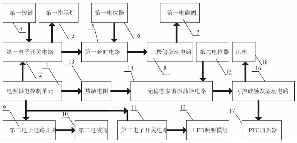
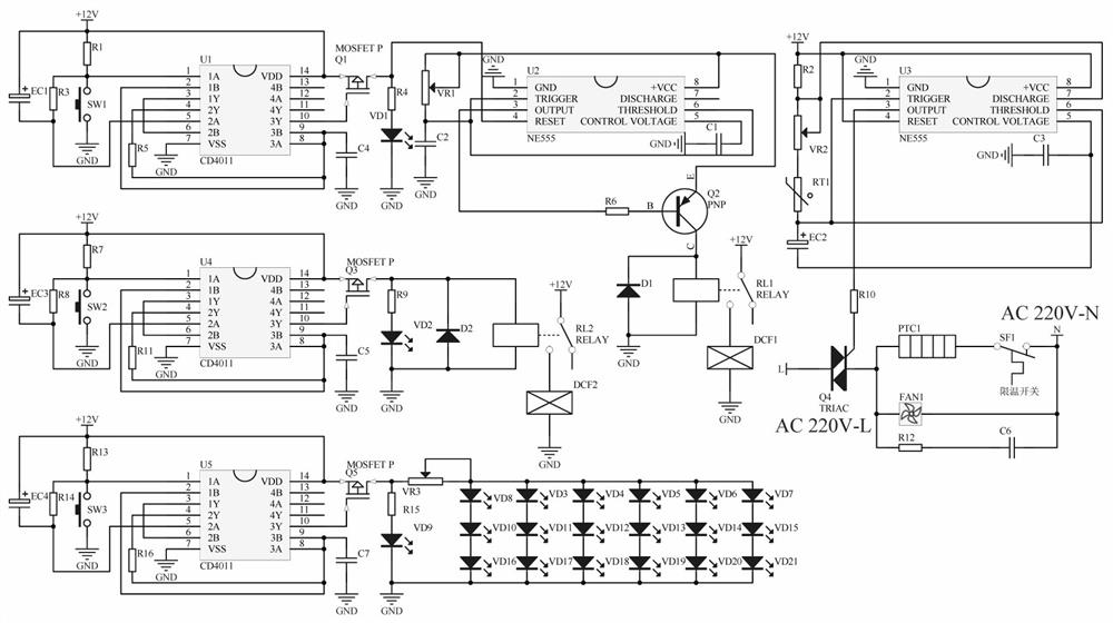
[0022] A blood extractor control circuit for routine blood tests, such as figure 1 As shown, it includes a power supply control unit 1, a thermistor 13, an astable multivibrator circuit 14, a second potentiometer 15, a thyristor trigger drive circuit 16, a PTC heater 17 and a fan 18, the The output end of the thermistor 13 is connected with the output end of the astable multivibrator circuit 14, and the input end of the astable multivibrator circuit 14 is connected with the output end of the second potentiometer 15, and the astable multivibrator circuit 14 is connected with the output end of the second potentiometer 15. The output end of the multivibrator circuit 14 is connected with the input end of the thyristor trigger driving circuit 16, the output end of the thyristor trigger driving circuit 16 is connected with the input end of the PTC heater 17, and the The output end is connected to the input end of the fan 18, and the power supply control unit 1 is a thermistor 13, an...

Embodiment 2

[0025] On the basis of Example 1, such as Figure 1-2 As shown, it also includes a second electronic circuit switch 9, a second solenoid valve 10, a third electronic switch circuit 11 and an LED lighting module 12, the output end of the second electronic circuit switch 9 is connected to the input of the second solenoid valve 10 The output end of the third electronic switch circuit 11 is connected to the input end of the LED lighting module 12. The power supply control unit 1 is the second electronic circuit switch 9, the second solenoid valve 10, and the third electronic switch circuit. 11 and LED lighting module 12 to supply power.

[0026] When the doctor draws blood from the patient, he needs to wipe the iodophor on the blood vessel of the patient. After the device is powered on, the second electronic circuit switch 9 controls the second solenoid valve 10 to work. The second solenoid valve 10 extracts the iodophor, and then controls the first The second solenoid valve 10 d...


PUM


Abstract

The invention relates to the field of medical treatment, in particular to a blood extractor control circuit for blood routine examination. The technical problem of the invention is to provide a control circuit of a blood extractor for smearing iodophor blood routine examination, wherein the control circuit can conveniently control the temperature of equipment and is used for smearing the iodophor blood routine examination. According to the technical scheme, the blood extractor control circuit for blood routine examination comprises a power supply control unit, a thermistor, an astable multivibrator circuit, a second potentiometer, a silicon controlled rectifier trigger drive circuit, a PTC heater and a fan, and the output end of the thermistor is connected with the output end of the astable multivibrator circuit. the input end of the astable multivibrator circuit is connected with the output end of the second potentiometer. by adjusting the PTC heater, air blown out by the fan can be heated, so that heat preservation can be performed on blood vessels of people, and a doctor can conveniently perform blood drawing work.

Description

technical field [0001] The invention relates to the medical field, in particular to a blood extractor control circuit for routine blood tests. Background technique [0002] Blood routine refers to the inspection of blood conditions and diseases by observing the changes in the number and morphology of blood cells. Many specific indicators in blood routine are some commonly used sensitive indicators. It is better to observe the treatment effect, take medicine or stop medicine, and continue treatment. Or the commonly used indicators of stopping treatment, disease recurrence or recovery. In the process of routine blood testing, the arms of the testing personnel need to be bound by rubber tubes to make it easier to find blood vessels. [0003] However, it is inconvenient to control the temperature of the equipment and apply iodophor in the process of blood extraction. Therefore, a blood extractor control circuit for routine blood testing that can be easily controlled and applied ...

Claims


Application Information

Patent Timeline
IPC IPC(8): A61F7/00A61M35/00H03K17/284A61B5/00
CPCA61F7/0053A61M35/20H03K17/284A61B5/489A61F2007/006A61F2007/0029A61M2210/04A61F2007/0095A61M2210/005
Inventor 黎丽英
Owner 黎丽英
Learn More