High-smoothness liquid supply pipeline

A liquid supply pipeline and smooth technology, applied in the direction of filtration and separation, separation method, mobile filter element filter, etc., can solve the problems of insufficient flow rate, affecting the flow rate and smoothness of the material liquid, unfavorable staff operation, etc., to reduce maintenance. and maintenance, improve service life, and ensure the effect of service life

Inactive Publication Date: 2021-08-24
江阴市锦绣江南环境发展有限公司
View PDF5 Cites 0 Cited by
  • Summary
  • Abstract
  • Description
  • Claims
  • Application Information

AI Technical Summary

Problems solved by technology

[0002] When the existing liquid supply pipeline is aimed at the material liquid with viscosity or impurities, when there are too many impurities or the viscosity is high, it will affect the smoothness of pipeline transportation, and at the same time, it will affect the use of pipelines and pumps on the pipeline. Lifespan and use effect
[0003] Now the pipeline filter can be used to filter the material liquid, but the pipeline filter uses a filter element, the flow rate is insufficient, which affects the smoothness of the material liquid, and the filter element needs to be cleaned or replaced or maintained for a long time, which is not conducive to the operation of the staff
[0004] At the same time, a viscosity detector can be installed on the pipe wall to detect the viscosity. When the viscosity exceeds the standard, it will affect the flow rate and smoothness of the feed liquid. However, the existing pipeline cannot quickly and effectively discharge or replace the feed liquid that exceeds the standard. , is not conducive to the operation of the staff

Method used


Image

  • High-smoothness liquid supply pipeline
  • High-smoothness liquid supply pipeline
  • High-smoothness liquid supply pipeline

Examples


Embodiment Construction

[0036] The following will clearly and completely describe the technical solutions in the embodiments of the present invention with reference to the accompanying drawings in the embodiments of the present invention. Obviously, the described embodiments are only some, not all, embodiments of the present invention. Based on the embodiments of the present invention, all other embodiments obtained by persons of ordinary skill in the art without creative efforts fall within the protection scope of the present invention.

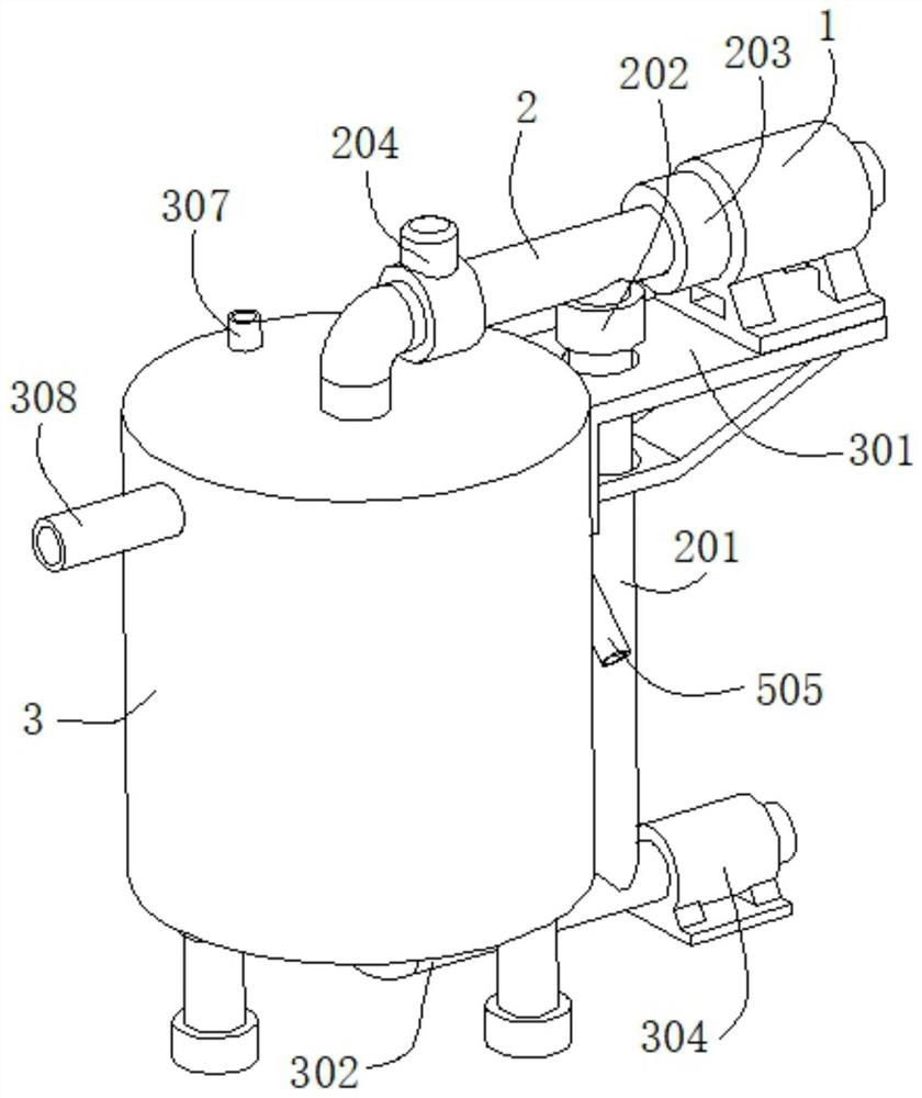
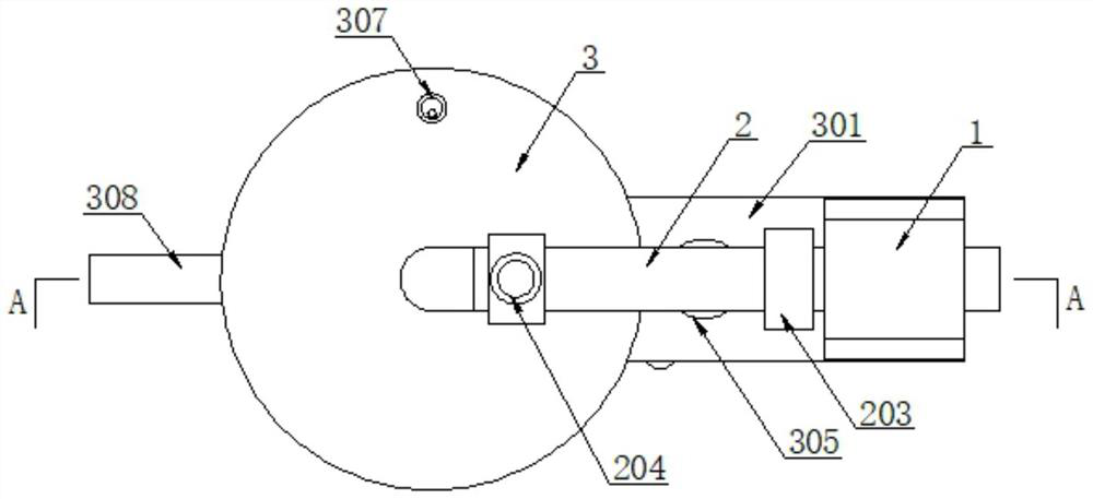
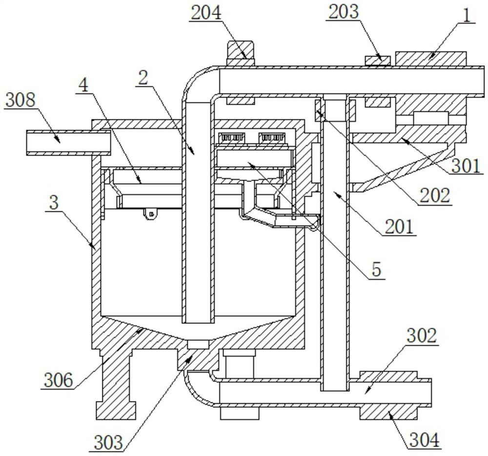
[0037] see Figure 1-5 As shown, the present invention is a high-fluid liquid supply pipeline, including a pump body 1, a liquid suction pipe 2, a water tank 3, a filter device 4 and a cleaning device 5;

[0038] One end of the suction pipe 2 runs through the water tank 3 and is located at the lower part of the water tank 3;

[0039] The filter device 4 includes a filter plate 401 and a drive mechanism 6;

[0040] One surface of the filter plate 401 is fixed with...


PUM


Abstract

The invention discloses a high-smoothness liquid supply pipeline, and relates to the technical field of pipeline systems. The device comprises a pump body, a liquid pumping pipe, a water tank, a filtering device and a cleaning device. One end of the liquid pumping pipe penetrates through the water tank and is positioned at the lower part in the water tank; the filtering device comprises a filtering plate and a driving mechanism; an inner sleeve body is fixed on one surface of the filter plate; the peripheral side surface of the inner sleeve body is rotationally connected with an outer sleeve body through a bearing; the jacket body is fixed at the upper part in the water tank; the driving mechanism is arranged between the inner sleeve body and the water tank, the cleaning device comprises a material collecting shell and a pressurizing shell, and the material collecting shell and the pressurizing shell are each of a shell structure with one face open. According to the invention, the water tank for detection and filtration is arranged at the position of the liquid extraction pipe of the pipeline, so that the feed liquid can be filtered and subjected to viscosity detection before being fed, and the situation of insufficient smoothness caused by more impurities or higher viscosity in the feed liquid is avoided; and meanwhile, the service life of the pump body and the pipeline in the pipeline can be prolonged, and blockage is reduced.

Description

technical field [0001] The invention belongs to the technical field of pipeline systems, in particular to a high-fluency liquid supply pipeline. Background technique [0002] When the existing liquid supply pipeline is aimed at the material liquid with viscosity or impurities, when there are too many impurities or the viscosity is high, it will affect the smoothness of pipeline transportation, and at the same time, it will affect the use of pipelines and pumps on the pipeline. Lifespan and use effect. [0003] Now the pipeline filter can be used to filter the feed liquid. However, the pipeline filter uses a filter element, and the flow rate is insufficient, which affects the smoothness of the feed liquid. At the same time, the filter element needs to be cleaned, replaced or maintained for a long time, which is not conducive to the operation of the staff. [0004] At the same time, a viscosity detector can be installed on the pipe wall to detect the viscosity. When the visco...

Claims


Application Information

Patent Timeline
Patent Type & Authority Applications(China)
IPC IPC(8): B01D33/15B01D33/46B01D33/74B01D33/76B01D33/80
CPCB01D33/15B01D33/466B01D33/74B01D33/76B01D33/80B01D33/807B01D33/804
Inventor 马忠贺陈琤
Owner 江阴市锦绣江南环境发展有限公司
Why Eureka
Try Eureka