[0030] Example:
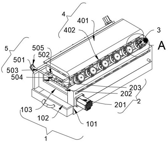
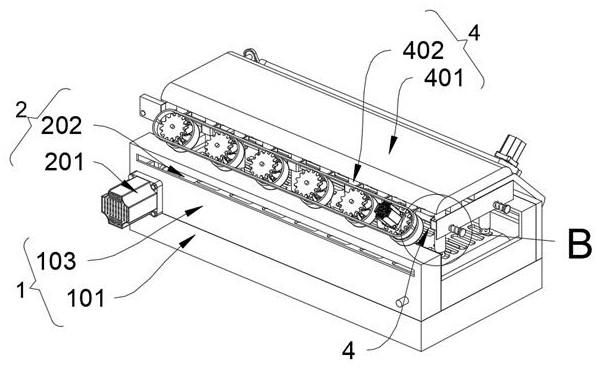
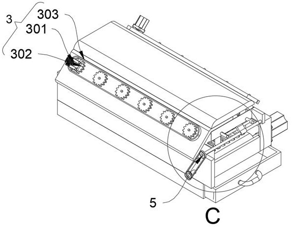
[0031] as attached figure 1 to attach Figure 8 Shown:
[0032] The invention provides a non-woven fabric return uncoiling device, comprising: a feeding mechanism 2, a dust removal mechanism 3 and a flushing mechanism 4, the feeding mechanism 2 is installed in the inner position of the bearing mechanism 1; the dust removal mechanism 3 is equipped with Two places, and the two dust removal mechanisms 3 are respectively installed on the left and right sides of the carrying mechanism 1; the flushing mechanism 4 is installed directly above the carrying mechanism 1 through the guiding mechanism 5; the guiding mechanism 5 also includes a shifting block 504 and The push rod 505 and the shift block 504 are socketed in the middle of the outer peripheral surface of the guide rod 503. There are two push rods 505, and the left ends of the two push rods 505 are arranged in a linear array. The square frame that the left end of 505 is installed is socketed in the outside position of airbag ball 403.
[0033] Wherein, the carrying mechanism 1 includes a base 101 , a waste box 102 and an operating platform 103 , the waste box 102 is plugged into the inner position of the base 101 , and the operating platform 103 is fixedly connected to the top surface of the base 101 .
[0034]Wherein, the feeding mechanism 2 includes a feeding motor 201, a conveyor belt 202 and a transmission shaft 203, two rollers of the same size are installed inside the conveyor belt 202, and a transmission shaft 203 is installed inside the two rollers, and the conveyor belt 202 There is a through slot inside, and the feeding motor 201 is installed on the front side of the transmission shaft 203 on the left side. In the installed state, the feeding motor 201 is fixedly connected to the front end of the console 103 .
[0035] Wherein, the dust removal mechanism 3 includes a dust removal motor 301 and a gear A302. There are six gears A302 in total, and the six gears A302 are arranged in a horizontal array, and the gear A302 on the right is installed at the bottom of the dust removal motor 301. When When the six gears A302 rotate, they can synchronously drive the dust removal fan 305 installed inside the casing 304 to rotate synchronously, and because the two groups of dust removal mechanisms 3 are designed with a symmetrical inclination of 45°, they can be placed on the conveyor belt by air convection. The dust attached to the non-woven fabric on the surface of the 202 is blown off, and is blown off through the operating table 103 to the internal position of the waste bin 102 inserted in the base 101 for collection.
[0036] Wherein, the dust removal mechanism 3 also includes a chain A303, a housing 304 and a dust removal fan 305, the chain A303 is meshed and driven at the outer positions of the six gears A302, and the dust removal fans 305 are provided with six places in total, and the outer sides of the six dust removal fans 305 are all A casing 304 is set, and gears A302 are installed on the oblique upper sides of the six dust removal fans 305 . In the installed state, two groups of dust removal fans 305 are symmetrically installed on the top left and right sides of the console 103 .
[0037] Wherein, flushing mechanism 4 comprises pump water tank 401, downpipe 402, airbag ball 403 and shower head 404, and downwater pipe 402 is installed in the bottom position of pump water box 401, and the middle section of downwater pipe 402 is equipped with airbag ball 403, sprays The shower head 404 is elastically connected to the inner bottom side of the downpipe 402, and the outer peripheral surface of the shower head 404 is provided with through holes in a circular array.
[0038] Wherein, the guide mechanism 5 includes a gear B501, a chain B502 and a guide rod 503. There are two gears B501, and the outer meshing transmission of the two gears B501 has a chain B502, and the guide rod 503 is installed on the gear B501 located on the upper side. and the gear B501 on the lower side is mounted on the rear side of the transmission shaft 203 on the left side.
[0039] When in use: first put the non-woven fabric to be returned on the conveyor belt 202 in the conveying mechanism 2 installed inside the base 101 of the carrying mechanism 1, and then start the conveying motor in the conveying mechanism 2 201 drives the friction transmission between the rollers installed on the outer peripheral surface and the conveyor belt 202 through the drive shaft 203 to drive the conveyor belt 202 to carry the non-woven fabric to the right side of the transport operation. The motor 301 drives the gear A302 installed at the output end to rotate, and drives the other five gears A302 to rotate synchronously through the meshing transmission between the gear A302 and the chain A303. When the six gears A302 rotate, they can be synchronously driven and installed on the The dust removal fan 305 inside the housing 304 rotates synchronously, and because the two groups of dust removal mechanisms 3 are designed with a symmetrical inclination of 45°, the non-woven fabric placed on the surface of the conveyor belt 202 can be placed on the surface of the non-woven fabric attached to it by air convection. The dust is blown off, and is blown off through the console 103 to the inner position of the waste box 102 inserted in the base 101 for collection;
[0040] On the other hand, a flushing mechanism 4 is also installed on the top of the console 103, wherein the downpipe 402 can drive the guide rod 503 to rotate synchronously through the meshing transmission between the gear B501 in the guide mechanism 5 and the chain B502, and then synchronously Drive the shifting block 504 sleeved on the outer peripheral surface of the guide rod 503 to rotate. When the shifting block 504 is in contact with the push rod 505, the left end of the two push rods 505 will be arranged in a straight line to form a square frame to the sewer pipe 402. The airbag ball 403 installed in the middle section performs a reciprocating extrusion operation, and then continuously squeezes the airbag ball 403 to draw water from the inside of the pump water tank 401, and then pushes the sprinkler head 404 from the downpipe through the impact force of the water flow. The inside of 402 is ejected to achieve the purpose of spraying water out of the through hole on the outer peripheral surface of the spray head 404 to rinse the non-woven fabric. Environmentally friendly cleaning operations can achieve more practical purposes.