Electric shoelace tying transmission device

A transmission device and a technology for tying shoelaces, applied in electromechanical devices, electric components, footwear, etc., can solve problems such as high self-locking precision requirements, difficult structure miniaturization, cumbersome and time-consuming processes, etc.

Pending Publication Date: 2021-08-27
深圳讯勉科技有限公司
View PDF0 Cites 0 Cited by
  • Summary
  • Abstract
  • Description
  • Claims
  • Application Information

AI Technical Summary

Problems solved by technology

[0002] Tying shoelaces is a common thing in people's daily life. Traditional shoelaces are done manually, and the process is relatively cumbersome and time-consuming.
Most of the existing patents for automatic shoelace

Method used


Image

  • Electric shoelace tying transmission device
  • Electric shoelace tying transmission device
  • Electric shoelace tying transmission device

Examples


Embodiment Construction

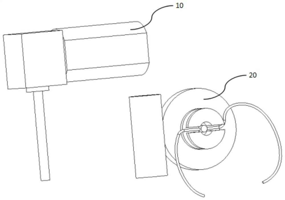
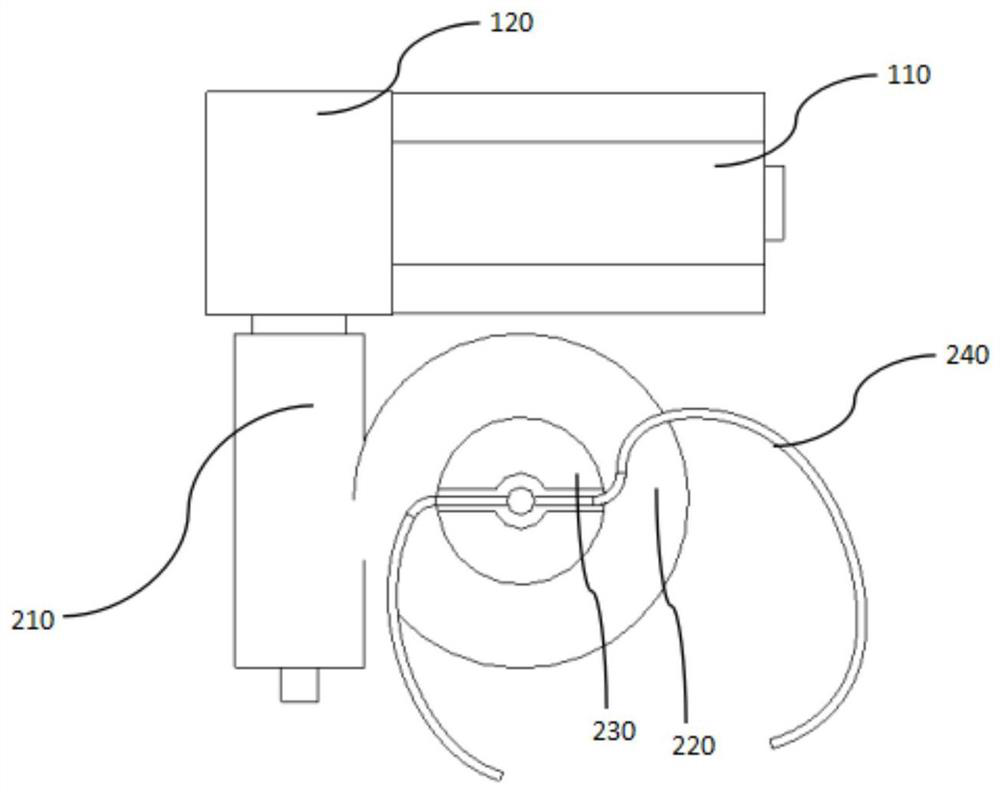
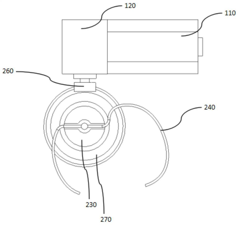
[0014] In order to make the purpose, technical solution and advantages of the invention clearer, the electric shoelace-tying transmission device of the present invention will be further described in detail below in conjunction with the accompanying drawings and embodiments. It should be understood that the specific embodiments described here are only used to explain the present invention, not to limit the present invention.

[0015] In the description of the present invention, unless otherwise stated, the orientations or positional relationships indicated by "clockwise", "countertrend", "axial", "left", "right" etc. are based on the orientations or positional relationships shown in the drawings The positional relationship is only for the convenience of describing the simplified description of the present invention, but does not indicate or imply that the referred device or element must have a specific orientation, be constructed and operated in a specific orientation, and thus ...


PUM


Abstract

The invention discloses an electric shoelace tying transmission device which is arranged on an automatic shoelace tying device. The device comprises a gear motor and a transmission assembly, the gear motor comprises a motor and a vertical speed reducer, and the transmission assembly comprises a driving component, a driven component, a winding ring and a shoelace, and the winding ring is coaxial with the driven component and fixed on the driven component. The motor shaft rotates to drive the output shaft of the vertical speed reducer to rotate and drive the driving component on the output shaft of the speed reducer to rotate so that the driven component is driven to rotate, the winding ring is driven to wind or unwind a shoelace, and the purposes of tying and loosening the shoelace are achieved.

Description

technical field [0001] The invention belongs to the field of shoes, in particular to a control device for automatically tying shoelaces. Background technique [0002] Tying shoelaces is a common thing in people's daily life. Traditional shoelaces are all done manually, and the process is relatively cumbersome and time-consuming. Most of the existing patents for automatic shoelace tying are complex in technology, difficult to implement, and difficult to miniaturize in structure. The use of screw threads to complete self-locking requires high precision, and the process is complicated and costly. Contents of the invention [0003] The technical problem to be solved by the present invention is to provide an electric shoelace transmission device, through a reasonable layout of the overall transmission device, the overall structure is simple and the space of the entire device is rationally used, and it can be placed on the automatic shoelace according to requirements. device an...

Claims


Application Information

Patent Timeline
IPC IPC(8): A43C11/16A43C1/00H02K7/116
CPCA43C1/00A43C11/165H02K7/1166
Inventor 黄凯
Owner 深圳讯勉科技有限公司
Why Eureka
Try Eureka