
Efficient forming process of snap spring

A forming process and circlip technology, applied in the field of circlip processing, can solve the problems of unsatisfactory wire bending effect, unguaranteed dimensional accuracy, wire breakage, etc. Effect of reset speed

Active Publication Date: 2021-08-27
绍兴市三阳弹簧股份有限公司
View PDF6 Cites 1 Cited by
  • Summary
  • Abstract
  • Description
  • Claims
  • Application Information

AI Technical Summary

Problems solved by technology

[0003] During the bending process of the circlip, metal wires of different diameters need to be bent. The traditional processing method is mostly to measure the size and mark the position, and then manually add tools to make it, which is time-consuming and laborious, and the dimensional accuracy cannot be guaranteed. It is difficult to control the bending force for wires of different diameters by means of the bending device for the circlip, resulting in the breakage of wires with smaller diameters and unsatisfactory bending effects of wires with larger diameters. We propose a high-efficiency forming process for circlips to solve the above problems

Method used


Image

  • Efficient forming process of snap spring
  • Efficient forming process of snap spring
  • Efficient forming process of snap spring

Examples


Embodiment Construction

[0034] The following will clearly and completely describe the technical solutions in the embodiments of the present invention with reference to the accompanying drawings in the embodiments of the present invention. Obviously, the described embodiments are only some, not all, embodiments of the present invention. Based on the embodiments of the present invention, all other embodiments obtained by persons of ordinary skill in the art without making creative efforts belong to the protection scope of the present invention.

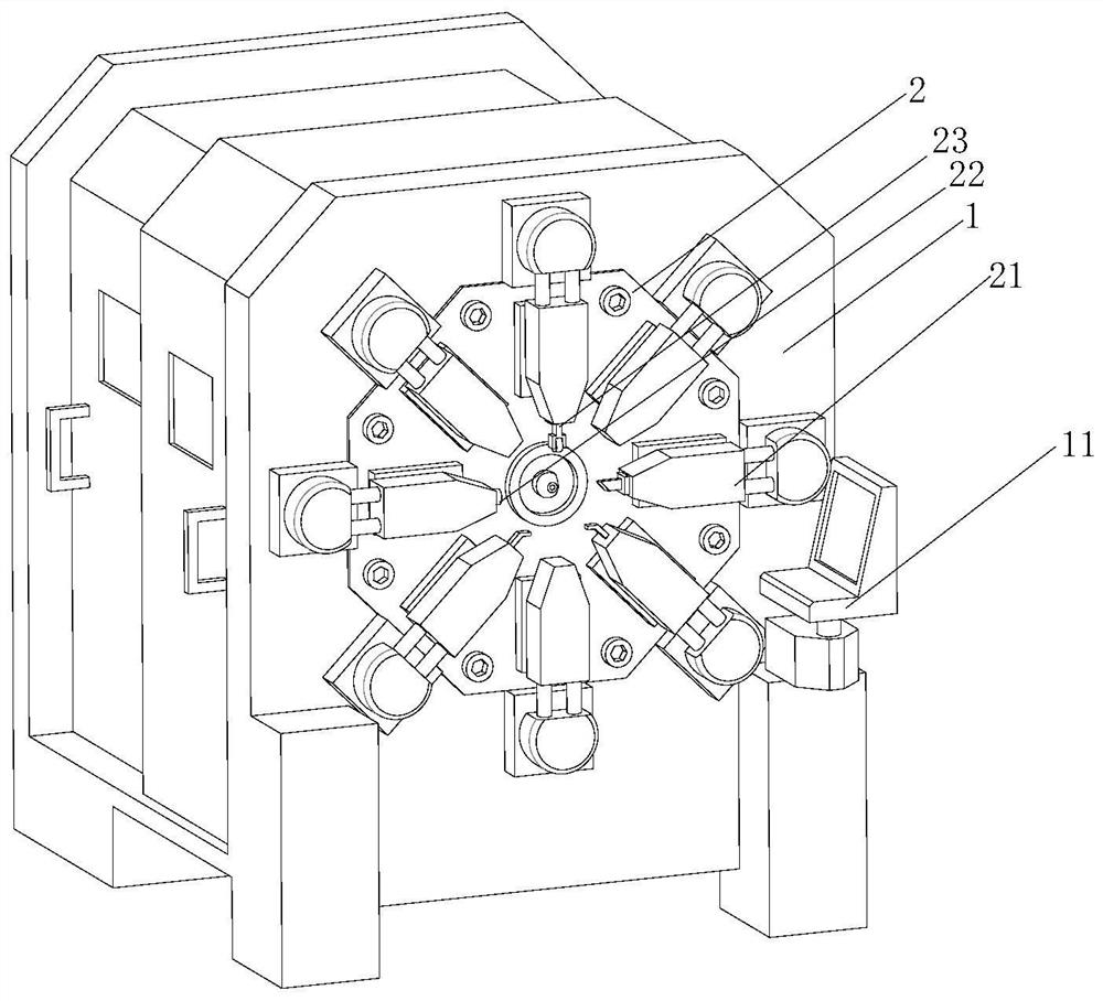
[0035] 3. See Figure 1-7 , the present invention provides a technical solution: a high-efficiency forming process for a circlip, which is characterized in that it consists of the following steps:

[0036] Step 1. First, the surface of the metal wire can be subjected to the force of outward movement under the action of the discharge device, and the metal wire to be processed is discharged through the discharge port from the direction away from the side of the fi...


PUM


Abstract

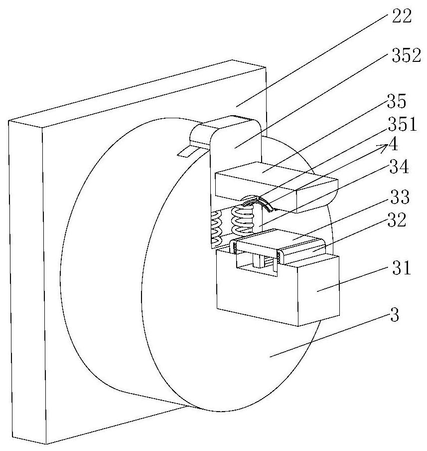
The invention discloses an efficient forming process of a snap spring. A forming device, a discharging device and a cutting device are included, a fixed disc is fixedly installed on the surface of the forming device, the discharging device comprises a discharging port, the discharging port is fixedly installed on the surface of the fixed disc, and a plurality of hydraulic cylinders are fixedly installed on the surface of the fixed disc; and a movable rod is fixedly mounted at the output end of each hydraulic cylinder, a connecting rod, a mounting plate and a limiting shaft are conical and fixedly connected to one end of each movable rod, the cutting-off device comprises a cutting-off knife, one end of the cutting-off knife is clamped on the movable rods on one sides, and a connecting seat is fixedly connected to one end of the mounting plate. Compared with the prior art, buffering blocks move inwards, special-shaped rods can be pushed to move in sliding grooves, the clamping plates can abut against the surface of a metal wire, the metal wire is driven to move along with movement of the buffering blocks, the situation that the metal wire is rapidly reset after being bent is avoided, and the situation that the bending effect is not ideal due to the fact that the diameter of the metal wire is large is reduced.

Description

technical field [0001] The invention relates to the technical field of circlip processing, in particular to a high-efficiency forming process of circlips. Background technique [0002] Circlips, also called retaining rings or clasps, are a type of fasteners, which are installed in the shaft grooves or hole grooves of machines and equipment, and play a role in preventing the axial movement of parts on the shaft or holes. [0003] During the bending process of the circlip, metal wires of different diameters need to be bent. The traditional processing method is mostly to measure the size and mark the position, and then manually add tools to make it, which is time-consuming and laborious, and the dimensional accuracy cannot be guaranteed. It is difficult to control the bending force for wires of different diameters by means of the bending device for the circlip, resulting in the breakage of wires with smaller diameters and unsatisfactory bending effects of wires with larger diam...

Claims


Application Information

Patent Timeline
Patent Type & Authority Applications(China)
IPC IPC(8): B21F35/00B21F11/00B21F1/00
CPCB21F1/004B21F11/00B21F35/00
Inventor 谢建钢谢建芬刘菊根赵飞魏正中李亮亮冯海锋
Owner 绍兴市三阳弹簧股份有限公司
Learn More