Rust removal equipment for rear cross beam in rear floor rear cross beam assembly and working method thereof

A technology for rear beams and rear floors, which is applied to metal processing equipment, manufacturing tools, used abrasive processing devices, etc., can solve the problems of low rust removal efficiency and inability to remove rust, so as to ensure the effect of rust removal and strengthen Fixed effects, cost reduction effects

Pending Publication Date: 2021-08-27
合肥至信机械制造有限公司
View PDF1 Cites 0 Cited by
  • Summary
  • Abstract
  • Description
  • Claims
  • Application Information

AI Technical Summary

Problems solved by technology

Utilizing the embodiment of the present invention can realize automatic derusting without manual derusting, can avoid the occurrence of silicosis caused by manual derusting, guarantee the health of workers, can also greatly reduce the labor intensity of workers, improve derusting efficiency, and derusting The rust is uniform and thorough, and the derusting effect is good, but the derusting device cannot derust multiple workpieces at the same time, and the derusting efficiency is not high

Method used


Image

  • Rust removal equipment for rear cross beam in rear floor rear cross beam assembly and working method thereof
  • Rust removal equipment for rear cross beam in rear floor rear cross beam assembly and working method thereof
  • Rust removal equipment for rear cross beam in rear floor rear cross beam assembly and working method thereof

Examples


Embodiment Construction

[0021] The following will clearly and completely describe the technical solutions in the embodiments of the present invention with reference to the accompanying drawings in the embodiments of the present invention. Obviously, the described embodiments are only some, not all, embodiments of the present invention. Based on the embodiments of the present invention, all other embodiments obtained by persons of ordinary skill in the art without creative efforts fall within the protection scope of the present invention.

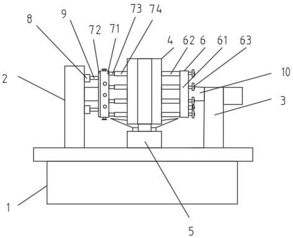
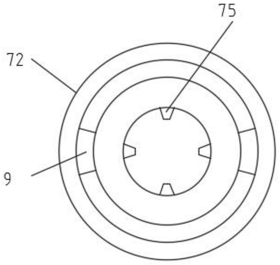
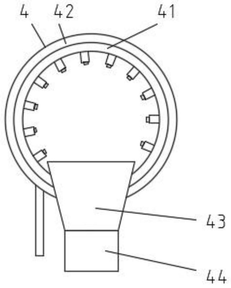
[0022] see Figure 1-5 As shown, a rust removal equipment for the rear crossbeam in the rear crossbeam assembly of the rear floor, including a collection mechanism 1, a column 2, a column 2 3, a derusting mechanism 4, a sand pump 5, a fixing mechanism 6, a cylinder 8, and a positioning rod 9. The rotating shaft 10, the upper end of the collection mechanism 1 is equipped with a load-bearing plate, and the upper end of the load-bearing plate is equipped with a column...


PUM


Abstract

The invention discloses rust removal equipment for a rear cross beam in a rear floor rear cross beam assembly and a working method thereof. The rust removal equipment comprises a collecting mechanism, a first stand column, a second stand column, a rust removal mechanism, a sand pump, a first fixing mechanism, an air cylinder, a positioning rod and a rotating shaft; a bearing plate is installed at the upper end of the collecting mechanism, and the first stand column, the second stand column, the rust removal mechanism and the sand pump are installed at the upper end of the bearing plate; the rust removal mechanism and the sand pump are both located between the first stand column and the second stand column, the second stand column is located at one side of the first stand column, the sand pump is located in front of the rust removal mechanism, the rotating shaft is rotationally installed between the first stand column and the second stand column and penetrates through the rust removal mechanism, and a rotating motor is arranged at one side of the second stand column; and the output end of the rotating motor penetrates through the second stand column to be connected with the rotating shaft, and the first fixing mechanism and a second fixing mechanism are installed on the outer surface of the rotating shaft. According to the rust removal equipment, multiple workpieces to be derusted can be derusted at the same time, and the derusting efficiency is improved.

Description

technical field [0001] The invention relates to the technical field of derusting automobile crossbeams, in particular to a rear crossbeam derusting device in a rear floor and rear crossbeam assembly and a working method thereof. Background technique [0002] Automobile rear beams may cause rust on the outer surface due to long storage time before assembly, so it needs to be derusted. A rust removal device is disclosed in the patent (CN109465722A), which includes a first drive part and a second drive part. , the first driving wheel, the first lead screw, the base and the derusting part for derusting, the first driving wheel engages with the first lead screw, the base includes a first fixed plate and a second fixed plate oppositely arranged, the The two ends of the first lead screw are respectively fixed on the first fixed plate and the second fixed plate, the first drive part drives the first drive wheel to move on the first lead screw, and the first drive wheel The derustin...

Claims


Application Information

Patent Timeline
IPC IPC(8): B24C1/08B24C5/04B24C9/00
CPCB24C1/086B24C5/04B24C9/00B24C9/006
Inventor 张俊虎牟维权刘培曹于姚静
Owner 合肥至信机械制造有限公司
Why Eureka
Try Eureka