Accurate positioning combined clamp used for guide pipe type part welding

A technology for welding and precise positioning of parts, which is used in household appliances, welding equipment, auxiliary welding equipment, etc., and can solve the problems of complex structure, inability to achieve protection, and the inner walls of the first conduit and the second conduit cannot be protected. Use effect and other issues to achieve the effect of avoiding use defects

Pending Publication Date: 2021-08-31
成都长之琳航空制造有限公司
View PDF0 Cites 0 Cited by
  • Summary
  • Abstract
  • Description
  • Claims
  • Application Information

AI Technical Summary

Problems solved by technology

[0002] The welding of conduit parts involves the positioning of two conduits, that is, the positioning of the first conduit and the second conduit. The technical bias in the prior art is that the positioning of the first conduit and the second conduit during welding is Clamping the outer wall of the first conduit and the second conduit for positioning, on the one hand causes the clamp to clamp the first conduit and the second conduit respectively, requiring the use of clamping tools, the structure is relatively complicated, and there is a problem with the first conduit and the second conduit The hidden danger of clip deformation, and the outer wall is usually welded during welding. If the inner wall of the first conduit and the second conduit are used in a complicated environment, the welding of this outer wall will not be better for the inner wall of the first conduit and the second conduit. The use effect of protection cannot be achieved by using the clamp for welding to play a protective use effect when the first conduit and the second conduit are welded and connected for a long time

Method used


Image

  • Accurate positioning combined clamp used for guide pipe type part welding
  • Accurate positioning combined clamp used for guide pipe type part welding
  • Accurate positioning combined clamp used for guide pipe type part welding

Examples


Embodiment Construction

[0015] The following will clearly and completely describe the technical solutions in the embodiments of the present invention with reference to the accompanying drawings in the embodiments of the present invention. Obviously, the described embodiments are only some, not all, embodiments of the present invention. Based on the embodiments of the present invention, all other embodiments obtained by persons of ordinary skill in the art without making creative efforts belong to the protection scope of the present invention.

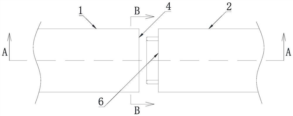
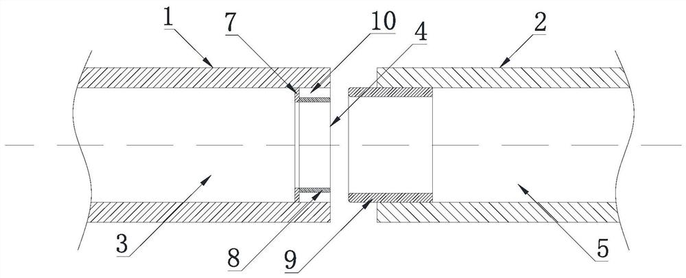
[0016] Please refer to the drawings in the description, the present invention provides a technical solution: a precise positioning combined fixture for welding conduit parts, including a first conduit 1 and a second conduit 2, the first conduit 1 includes a first channel 3 and a second conduit One end opening 4, the second conduit 2 includes a second channel 5 and a second end opening 6, the precise positioning combined fixture for welding conduit parts also in...


PUM


Abstract

The invention discloses an accurate positioning combined clamp used for guide pipe type part welding. The accurate positioning combined clamp comprises a first guide pipe and a second guide pipe, the first guide pipe comprises a first channel and a first end opening, and the second guide pipe comprises a second channel and a second end opening. The accurate positioning combined clamp used for guide pipe type part welding further comprises a connecting ring, a limiting ring and a positioning ring, an annular clamping groove is located in the position close to the end opening of the first guide pipe, the positioning ring cooperates with the annular clamping groove and comprises an annular outer side wall, one annular end and the other annular end, the position, close to one annular end, of the annular outer side wall of the positioning ring stretches into the second channel and is fixedly connected with the inner side wall of the second channel, and the other annular end of the positioning ring is connected with the annular clamping groove in a clamped manner. Technical prejudice existing in the prior art is overcome, existing deformation hidden dangers are reduced, and the clamp for welding achieves the use effect of protection when the first guide pipe and the second guide pipe are used for a long time after being welded and connected.

Description

technical field [0001] The invention relates to a precise positioning combined fixture for welding conduit parts, and belongs to the technical field of welding processing of conduit parts. Background technique [0002] The welding of conduit parts involves the positioning of two conduits, that is, the positioning of the first conduit and the second conduit. The technical bias in the prior art is that the positioning of the first conduit and the second conduit during welding is Clamping the outer wall of the first conduit and the second conduit for positioning, on the one hand causes the clamp to clamp the first conduit and the second conduit respectively, requiring the use of clamping tools, the structure is relatively complicated, and there is a problem with the first conduit and the second conduit The hidden danger of clip deformation, and the outer wall is usually welded during welding. If the inner wall of the first conduit and the second conduit are used in a complicate...

Claims


Application Information

Patent Timeline
Patent Type & Authority Applications(China)
IPC IPC(8): B23K37/053B23K101/06
CPCB23K37/0531B23K2101/06
Inventor 陆绍炳张强徐志强
Owner 成都长之琳航空制造有限公司
Why Eureka
Try Eureka