Full-automatic intelligent CCD (Charge Coupled Device) detecting and assembling equipment
An assembly equipment, fully automatic technology, applied in assembly machines, metal processing equipment, metal processing and other directions, can solve the problems of slow production efficiency, easy processing errors, small fuses, etc., to achieve high production efficiency, ensure high quality, and be less error-prone Effect
- Summary
- Abstract
- Description
- Claims
- Application Information
AI Technical Summary
Problems solved by technology
Method used
Image


Examples
Embodiment approach
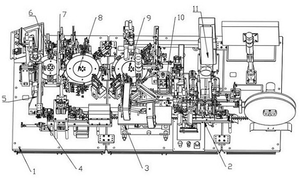
[0030] Such as Figure 1-Figure 8 One embodiment described: a fully automatic intelligent CCD detection and assembly equipment, including a frame 1, on which a feeding device 2, a cleaning device 3, a transfer device 4, a single-chip conveying device 5, a folding Bending device 6, crimping device 7, first feeding device 8, second feeding device 9, welding device 10 and marking device 11, the feeding device 2, cleaning device 3 and transfer device 4 are sequentially from right to left It is arranged in parallel on the frame 1, the welding device 10 is arranged on the rear side of the feeding device 2, the marking device 11 is arranged on the rear side of the welding device 10, and the first feeding device 4 is arranged on the rear side of the transfer device 4 respectively. Device 8, second feeding device 9, crimping device 7 and bending device 6, the bending device 6, crimping device 7, first feeding device 8 and second feeding device 9 are in order from left to right Arranged ...
Embodiment 2
[0041] Embodiment 2 is different from the above in that the second feeding device 9 includes an upper cover assembly, a second detection device, a disk assembly and a take-out assembly, and the upper cover assembly, the second detection device, the disk assembly and The extraction components are all arranged on the frame 1, the upper cover assembly is arranged on the right side of the disk assembly, the second detection device is arranged on the rear side of the disk assembly, and the extraction assembly is arranged on the the front side of the disk assembly.
Embodiment 3
[0042] Embodiment 3 is different from the above in that the upper cover assembly includes a upper cover support, a cover vibrator, a cover transfer device, a cover gripper and a cover support plate, and the cover support is arranged on the On the frame, the upper cover vibrator is arranged on the frame through the vibrating bottom plate, the output end of the upper cover vibrator is arranged on the lower surface of the upper cover support, and the upper cover transfer device is arranged on the On the upper cover support, the upper cover support plate is arranged on the upper cover transfer device, the fixed end of the upper cover gripper is arranged on the upper cover support plate, and the upper cover clamp is arranged on the output end of the upper cover gripper claw.
PUM
 Abstract
Description
Claims
Application Information