Simple adjustable bench clamp

An adjustable, vise technology, used in vices, manufacturing tools, etc., can solve problems such as poor clamping adaptability, and achieve the effects of stable clamping, high clamping quality and a wide range of equipment applications

Pending Publication Date: 2021-08-31
霍山嘉远智能制造有限公司
View PDF8 Cites 1 Cited by
  • Summary
  • Abstract
  • Description
  • Claims
  • Application Information

AI Technical Summary

Problems solved by technology

[0004] The purpose of the present invention is to solve the problem of poor clamping adaptability in the prior art, and propose a simple and adjustable vise

Method used


Image

  • Simple adjustable bench clamp
  • Simple adjustable bench clamp
  • Simple adjustable bench clamp

Examples


Embodiment

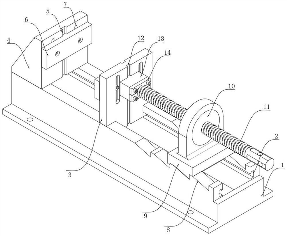
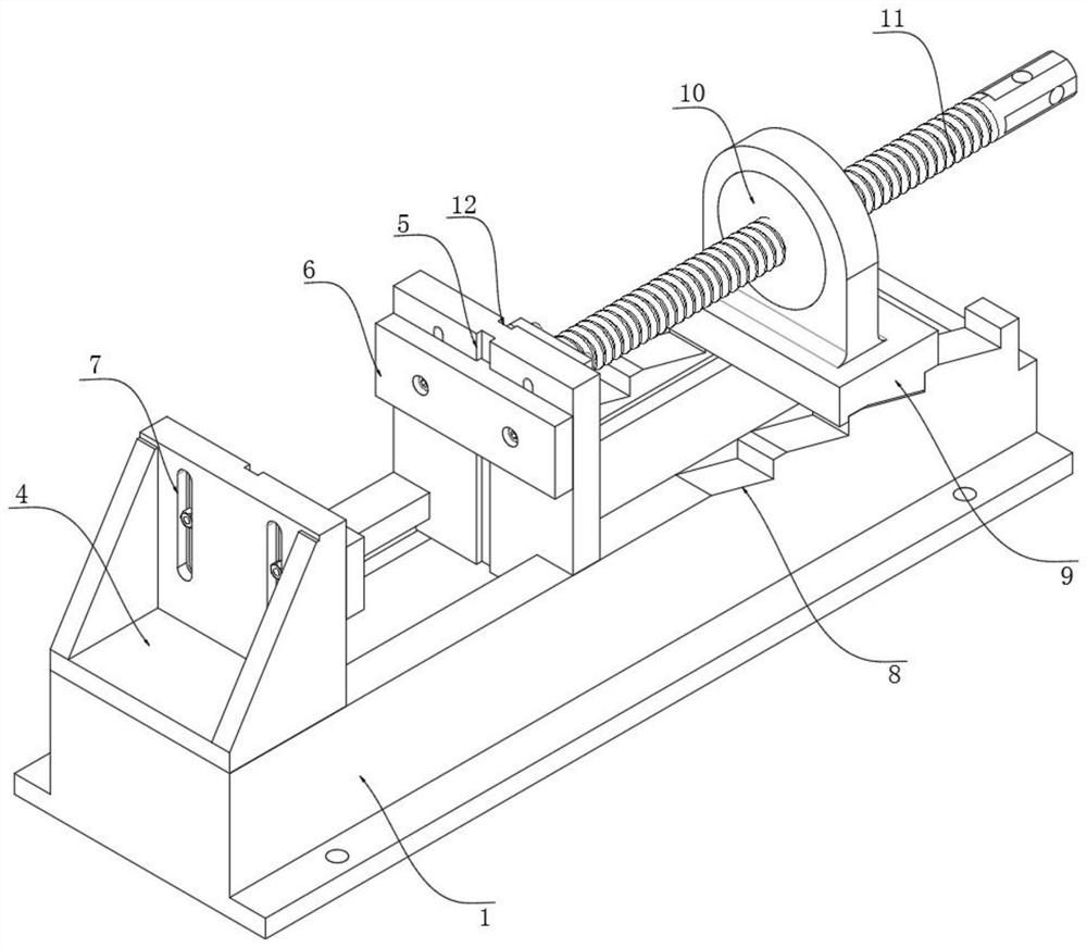
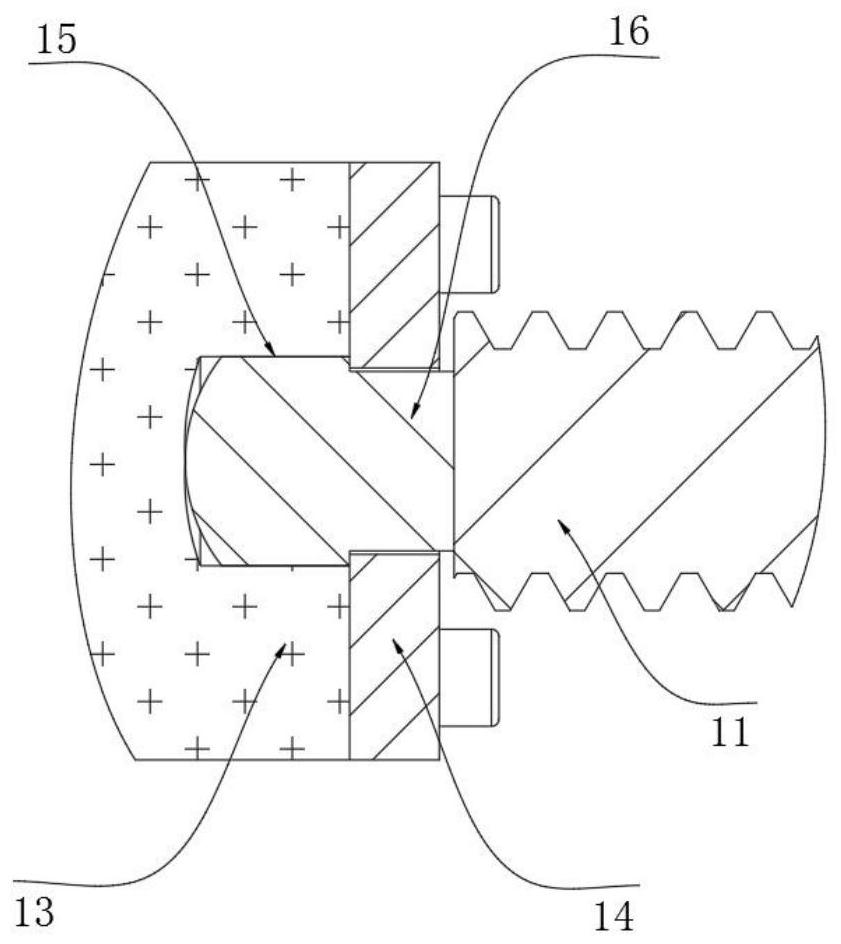
[0026] refer to Figure 1-3 , a simple adjustable vise, including a base 1, the side wall of the base 1 is provided with a chute 2, the inner wall of the chute 2 is slidably connected with a moving backing plate 3, the upper end of the base 1 is fixed with a fixed backing plate 4, and the moving backing The side walls of the plate 3 and the fixed backing plate 4 are equipped with a positioning and clamping mechanism, and the upper end of the base 1 is provided with a tooth socket 8, and the upper end of the tooth socket 8 is offset by a supporting tooth block 9, and the upper end of the supporting tooth block 9 is fixed with an adjustable support 10. The side wall of the adjustment support 10 is threadedly connected with a propulsion screw 11 , and the end of the propulsion screw 11 is connected with a propulsion coupling mechanism.

[0027] The positioning and clamping mechanism includes balance grooves 5 opened on the side walls of the movable backing plate 3 and the fixed b...

Embodiment 2

[0032] refer to Figure 4-5The difference between this embodiment and Embodiment 1 is that the advancement process is improved. The inner wall of the base 1 is connected with a screw 18 for rotation, and the side wall of the screw 18 is threaded with a slide plate 22. The movement of the slide plate 22 will drive the wire The rotation of bar 18, the upper end of slide plate 22 is fixed with hydraulic box 23, and the inner wall of hydraulic box 23 is sealed and slidably connected with push plate 27, and push block 13 penetrates the side wall of hydraulic box 23 and is fixed with the side wall of push plate 27, pushes The plate 27 and the inner wall of the hydraulic box 23 are jointly fixed with a drive spring 26, the side wall of the hydraulic box 23 is fixed with an extrusion box 24, and the inside of the extrusion box 24 is provided with a positioning and advancing mechanism, and the inner wall of the synchronous groove 12 is slidingly connected with a force Block 25, the for...


PUM


Abstract

The invention discloses a simple adjustable bench clamp. The simple adjustable bench clamp comprises a base, wherein a sliding groove is formed in the side wall of the base, a movable backup plate is slidably connected to the inner wall of the sliding groove, a fixed backup plate is fixed to the upper end of the base, positioning clamping mechanisms are arranged on the side wall of the movable backup plate and the side wall of the fixed backup plate, and tooth grooves are formed in the upper end of the base; and the upper ends of the tooth grooves abut against a supporting tooth block, an adjusting support is fixed to the upper end of the supporting tooth block, the side wall of the adjusting support is connected with a propelling screw in a penetrating and threaded manner, and the end of the propelling screw is connected with a propelling combination mechanism. The simple adjustable bench clamp has the advantages that clamping plates are locked through mounting bolts of the clamping plates, and the bolts for mounting the clamping plates penetrate through positioning kidney-shaped holes, so that the clamping plates can adapt to any position of the clamping plates in the range of the positioning kidney-shaped holes, mounting and position adjustment of the clamping plates cannot conflict, and meanwhile, a stress point in the height direction of a workpiece can be adjusted, and the workpiece can be clamped more stably.

Description

technical field [0001] The invention relates to the technical field of mechanical tools, in particular to a simple adjustable vise. Background technique [0002] Bench vise, also known as vise and bench vise, is a tool for clamping and fixing workpieces for processing, and is widely used. It also has more varieties. The vise is an essential tool for the fitter, and it is also the source of the name of the fitter, because most of the work of the fitter is done on the vise, such as sawing, filing, chiseling, and the assembly and disassembly of parts. The vise is installed on the fitter's table, and the width of the jaw is used as the calibration specification, and the common specifications are from 75mm to 300mm. [0003] Existing vises generally use fixed strokes and fixed specifications, and their function also has certain restrictions on the size of the workpiece according to the size of the vise. If it is necessary to complete the operation of workpieces of different siz...

Claims


Application Information

Patent Timeline
Patent Type & Authority Applications(China)
IPC IPC(8): B25B1/02B25B1/10B25B1/18B25B1/24
CPCB25B1/02B25B1/10B25B1/18B25B1/24
Inventor 潘义成杜应流万继升
Owner 霍山嘉远智能制造有限公司
Why Eureka
Try Eureka