
Tracking type energy-saving monitoring camera

A surveillance camera, tracking technology, applied in image communication, traffic control system, traffic control system of road vehicles, etc., can solve the problem of timely capture of illegal vehicles and pedestrians, limited monitoring range, and inability to effectively capture real-time conditions at traffic intersections and other problems, to achieve the effect of increasing the clarity and monitoring effect, and improving the monitoring range

Inactive Publication Date: 2021-08-31
烟台华皓电子科技有限公司
View PDF12 Cites 0 Cited by
  • Summary
  • Abstract
  • Description
  • Claims
  • Application Information

AI Technical Summary

Problems solved by technology

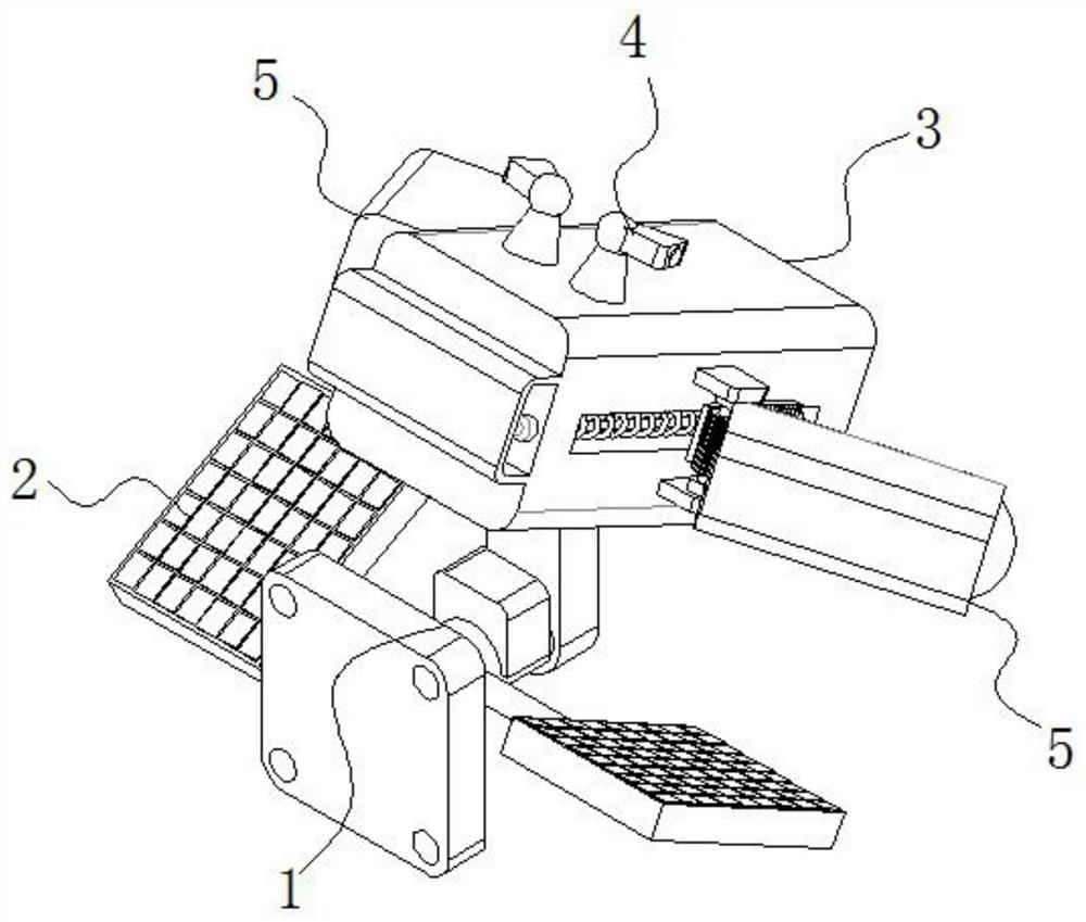
[0004] The purpose of the present invention is to provide a tracking type energy-saving monitoring camera, through the main monitoring probe, infrared detector, auxiliary monitoring probe, driving tooth plate, threaded rod, push plate, rotating shaft, tooth column, limit groove, return spring and The design of the focusing part solves the problem that most of the existing road monitoring cameras are installed in a fixed position, and the monitoring angle cannot be adjusted flexibly. When monitoring traffic intersections, it is easy to produce monitoring blind spots, and cannot effectively capture the real-time situation of traffic intersections. The monitoring range of road monitoring cameras is limited, and it is impossible to realize traffic monitoring in a large area, which greatly reduces the scope of application of traffic monitoring cameras, which in turn affects the timely capture of illegal vehicles and pedestrians

Method used


Image

  • Tracking type energy-saving monitoring camera
  • Tracking type energy-saving monitoring camera
  • Tracking type energy-saving monitoring camera

Examples


Embodiment 1

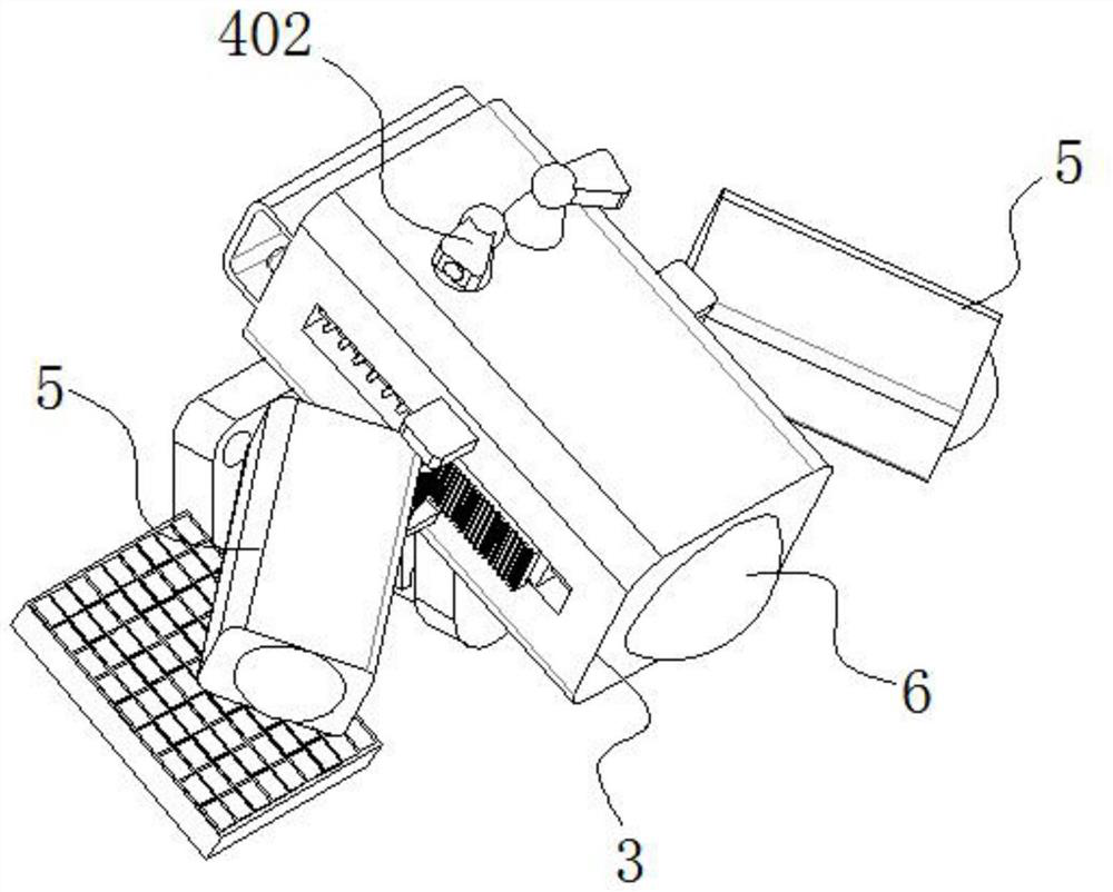
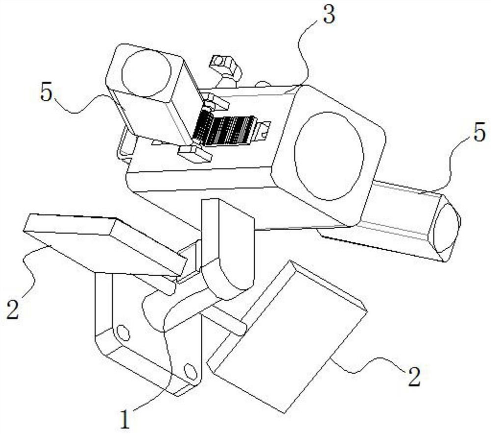
[0037] see Figure 1-8 , the present invention is a tracking type energy-saving surveillance camera, comprising a mounting mechanism 1;

[0038] Photovoltaic panels 2 are fixedly installed on both sides of the installation mechanism 1, and the photovoltaic panels 2 are used to convert solar energy into electrical energy and store it for the power supply of the camera;

[0039] The top of the installation mechanism 1 is fixed with a main monitoring probe 3 for monitoring the main area of ​​the traffic intersection; the top of the main monitoring probe 3 is symmetrically fixed with two sensing components 4 for sensing pedestrians or vehicles;

[0040] Both sides of main monitoring probe 3 are rotatably connected with auxiliary monitoring probe 5, and the monitoring area of ​​auxiliary monitoring probe 5 overlaps with the monitoring area of ​​main monitoring probe 3; When the component 4 senses pedestrians or vehicles, the auxiliary monitoring probe 5 is turned on, and the corre...


PUM


Abstract

The invention discloses a tracking type energy-saving monitoring camera, belonging to the technical field of monitoring. The tracking type energy-saving monitoring camera comprises a mounting mechanism, wherein photovoltaic panels are fixedly mounted on the two sides of the mounting mechanism; a main monitoring probe is fixedly mounted at the top of the mounting mechanism; two sensing assemblies are symmetrically fixed to the top of the main monitoring probe; the two sides of the main monitoring probe are rotationally connected with auxiliary monitoring probes; the auxiliary monitoring probes are matched with the sensing assemblies in position; and focusing parts are fixedly mounted at lenses of the main monitoring probe and the auxiliary monitoring probes. Through the design of the main monitoring probe, an infrared detector, the auxiliary monitoring probes, a driving toothed plate, a threaded rod, a push plate, a rotating shaft and a toothed column, as the threaded rod is rotated, the driving toothed plate is driven to move through the threaded matching effect of the threaded rod and the push plate, and under the meshing of the driving toothed plate and the toothed column, the monitoring areas of the auxiliary monitoring probes are moved to the monitoring area of the main monitoring probe, so tracking shooting of vehicles and pedestrians at a traffic intersection is realized.

Description

technical field [0001] The invention belongs to the technical field of monitoring, in particular to a tracking type energy-saving monitoring camera. Background technique [0002] Surveillance camera is a kind of quasi-camera equipment that can obtain video images for security. It is widely used in mobile phones, children's toys, aerospace aerial photography, automatic driving, robots, smart medical care, commercial retail, human-computer interaction and other in-depth behavior and remote monitoring. Chain business, large factory computer rooms, remote care for the elderly and children, public buildings, unmanned dangerous environment monitoring, branch monitoring of various financial institutions, traffic supervision, false alarm identification and other fields of education, commerce, medical care, and public utilities. In order to manage road traffic, a variety of surveillance cameras are installed on the road to detect traffic, capture illegal parking, monitor violations, ...

Claims


Application Information

Patent Timeline
Patent Type & Authority Applications(China)
IPC IPC(8): G08G1/017G08G1/04H04N5/247H04N5/232F16M11/04F16M11/06F16M11/18H04N23/90
CPCG08G1/0175G08G1/04F16M11/043F16M11/06F16M11/18H04N23/67H04N23/90
Inventor 朱凯旋
Owner 烟台华皓电子科技有限公司
Learn More