Electric shockproof hammer convenient to install

An anti-vibration hammer and electric power technology, applied in the direction of mechanical vibration damping device, etc., can solve problems such as the risk of bolt installation process, and achieve the effect of simplifying the installation process and the connection structure.

Active Publication Date: 2021-08-31
GUIZHOU POWER GRID CO LTD
View PDF8 Cites 1 Cited by
  • Summary
  • Abstract
  • Description
  • Claims
  • Application Information

AI Technical Summary

Problems solved by technology

[0003] However, since the installation position of the anti-vibration hammer has a certain distance from the tower where the staff is located, it is necessary for the staff to release all the safety belts and then stretch out the body for long-distance installation. The cables are tightly connected, and the installation process of screwing the bolts is extremely risky
In order to improve the installation dilemma of the existing anti-vibration hammer, an electric anti-vibration hammer that is easy to install is proposed

Method used


Image

  • Electric shockproof hammer convenient to install
  • Electric shockproof hammer convenient to install
  • Electric shockproof hammer convenient to install

Examples


Embodiment 1

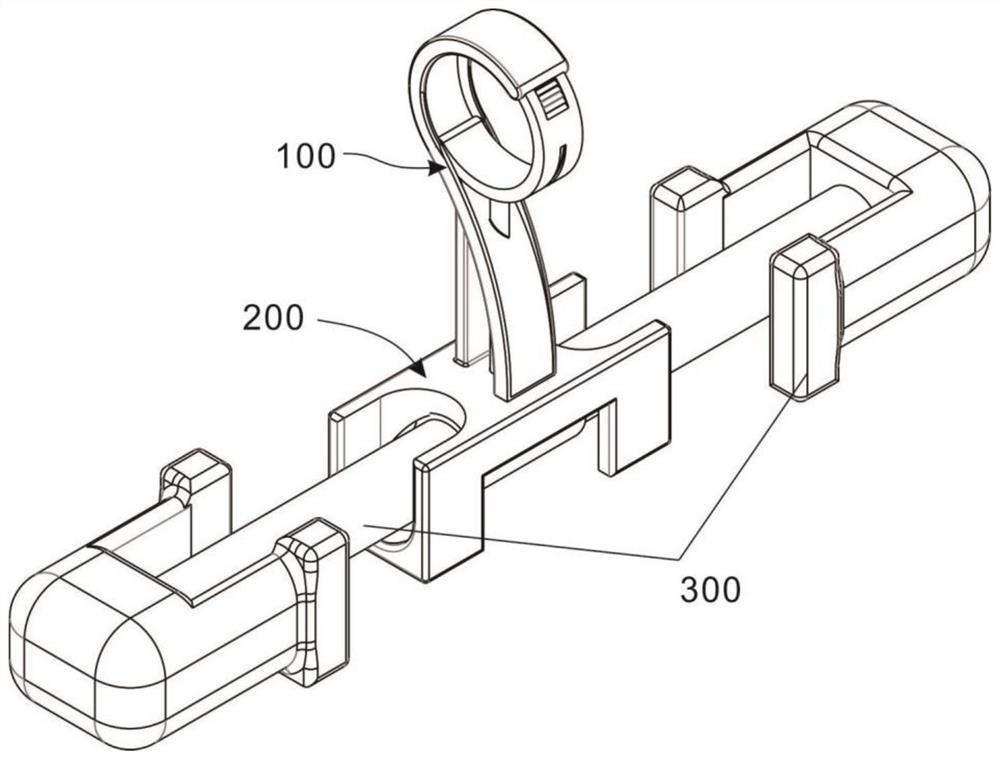
[0033] refer to figure 1 and 2 , as the first embodiment of the present invention, an electric anti-vibration hammer that is easy to install is provided, and the anti-vibration hammer includes a clamp unit 100 , a connection unit 200 and a hammer head unit 300 . Among them, the clamp unit 100 is the part of the anti-vibration hammer used to clamp the power cable, that is, the head of the anti-vibration hammer; the connection unit 200 is used to connect the clamp unit 100 and the hammer unit 300; the hammer unit 300 is a traditional anti-vibration hammer The hammer head style is used to reduce the vibration on the power cable. Further, the hammer head unit 300 is used to provide the driving force when the clamp unit 100 is clamped. The difference from the traditional anti-vibration hammer is that the hammer at both ends The head is a split structure.

[0034] Specifically, the wire clamp unit 100 includes a wire clamp hook 101 and an arc-shaped clamping plate 102 connected to...

Embodiment 2

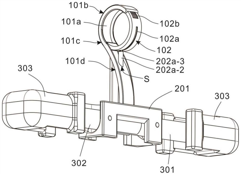
[0038] refer to figure 1 , 2 , 4 and 6 are the second embodiment of the present invention. This embodiment is different from the first embodiment in that: the clamp hook 101 has a limiting groove 101a along its plate side wall, and the limiting groove 101a Distribute the side of the plate body of the wire clamp hook 101; the wire clamp hook 101 is divided into a bending part 101b, a neck 101c and a connecting part 101d from top to bottom as a whole, and the limiting groove 101a starts from the end of the bending part 101b and finally connects The bottom of the part 101d; the sidewall of the neck 101c is provided with a through hole S; the connecting part 101d is fixed on the top sidewall of the connecting shell 201 .

[0039] An assembly groove 101e is provided in the limit groove 101a at the end of the bending portion 101b, and the limit fastener 103 is installed in the assembly groove 101e; the assembly groove 101e is divided into a first end 101e-1 and a second end 101e-2,...

Embodiment 3

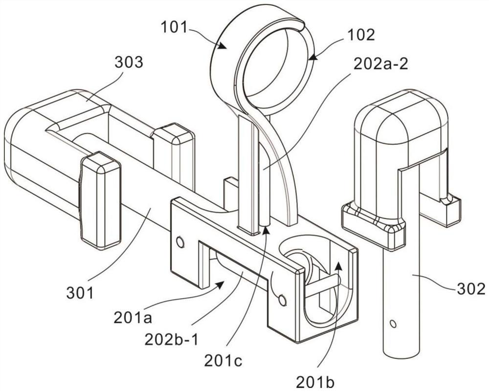
[0049] refer to Figure 1-7 , which is the third embodiment of the present invention. This embodiment is different from the second embodiment in that: a mounting groove 201a is opened in the side wall of the lower end of the connection housing 201, and limiting grooves 201b are symmetrically opened on the side walls of both ends. , and a connecting hole 201c is opened on the side wall of the middle part thereof.

[0050] The connection assembly 202 includes a driving part 202a and a connecting part 202b, both of which are mated and connected. One end of the driving part 202a is located in the installation groove 201a, the other end extends in the wire clip hook 101, and the connecting part 202b is arranged in the installation groove 201a.

[0051] The driver 202a includes an arc-shaped drive plate 202a-1 and a drive rod 202a-2 connected to the top side wall of the arc-shaped drive plate 202a-1, wherein the arc-shaped drive plate 202a-1 is located in the installation groove 201...


PUM


Abstract

The invention discloses an electric stockbridge hammer convenient to install. The electric stockbridge hammer comprises: a wire clamp unit which comprises a wire clamp hook and an arc-shaped clamping plate cooperatively connected with the wire clamp hook, wherein the wire clamp hook is internally provided with a limiting fastener, and the limiting fastener is connected with the side wall of the arc-shaped clamping plate; a connecting unit arranged at the bottom of the wire clamp hook and comprising a connecting shell and a connecting assembly arranged in the connecting shell; and hammerhead units which are symmetrically arranged on the two sides of the connecting unit, wherein each hammerhead unit comprises a first connecting rod, a second connecting rod and hammerheads arranged at the ends of the two connecting rods. The wire clamp unit is of a movable clamping structure, a movable arc-shaped clamping plate of the wire clamp unit is driven by the connecting unit, and the driving force of the connecting unit comes from the deflection effect when the hammer head is placed; and when the hammerheads are placed from a vertical state to a horizontal state, the connecting rod bodies of the hammer heads push the driving rod to move upwards so as to push the arc-shaped clamping plate to be inserted into the wire clamp hook, and the arc-shaped clamping plate and the wire clamp hook are clamped on a power cable together, so that a stable clamping structure is formed.

Description

technical field [0001] The invention relates to the technical field of electric auxiliary fittings, in particular to an electric anti-vibration hammer that is easy to install. Background technique [0002] The span of the high-voltage overhead line is large, and the tower is also high. When the wire is blown by a strong wind, a strong vibration will occur. When the conductor vibrates, the working conditions are the most unfavorable where the conductor hangs. Long-term and periodic vibration will cause fatigue damage to the wires, causing strands and wires to break. Sometimes strong shocks can damage hardware and insulators. In order to prevent and reduce the vibration of the wire, a certain number of anti-vibration hammers are generally installed near the suspension wire clamp. When the wire vibrates, the anti-vibration hammer also moves up and down. Generate a force that is asynchronous or even opposite to the vibration of the conductor, which can reduce the vibration a...

Claims


Application Information

Patent Timeline
Patent Type & Authority Applications(China)
IPC IPC(8): H02G7/14
CPCH02G7/14
Inventor 肖远奇游运郭如意黄杰王磊岳廷学杨伦惠陈忠磊李海平陈治宇徐骞聂量何鹏李可谢卿杨熔徐龙
Owner GUIZHOU POWER GRID CO LTD
Why Eureka
Try Eureka