Intelligent detection equipment for ophthalmology department

An intelligent detection and ophthalmology technology, applied in the fields of eye testing equipment, medical science, diagnosis, etc., can solve the problems of deviation of results, complex eye structure, and difficulty of the detection lens of the detection equipment facing the center of the eye, so as to reduce the tedious work. degree, improve intelligence, improve the effect of accuracy

Active Publication Date: 2021-09-03
NEUSOFT INST GUANGDONG +3
View PDF7 Cites 0 Cited by
  • Summary
  • Abstract
  • Description
  • Claims
  • Application Information

AI Technical Summary

Problems solved by technology

[0002]The eye is one of the important organs of the human body. In order to have a clearer understanding of the eye, people usually choose to have the eye tested in an eye medical testing institution. However, due to the The structure is relatively complicated, and it is difficult for the detection lens of the detection equipment to face the center of the eye. In addition, when facing collective ophthalmology detection, the detection doctor will often become tired due to too many personnel detection, and sometimes get stuck in the detection process. Empiricism, it is difficult to make the detection lens directly at the center of the human eye, resulting in some deviations in the results

Method used


Image

  • Intelligent detection equipment for ophthalmology department
  • Intelligent detection equipment for ophthalmology department
  • Intelligent detection equipment for ophthalmology department

Examples


Embodiment Construction

[0015] The technical solutions in the embodiments of the present invention will be clearly and completely described below in conjunction with the accompanying drawings in the embodiments of the present invention. Obviously, the described embodiments are only some of the embodiments of the present invention, not all of them; based on The embodiments of the present invention and all other embodiments obtained by persons of ordinary skill in the art without making creative efforts belong to the protection scope of the present invention.

[0016] It should be noted that the words "front", "rear", "left", "right", "upper" and "lower" used in the following description refer to the directions in the drawings, and the words "inner" and "outer ” refer to directions towards or away from the geometric center of a particular part, respectively.

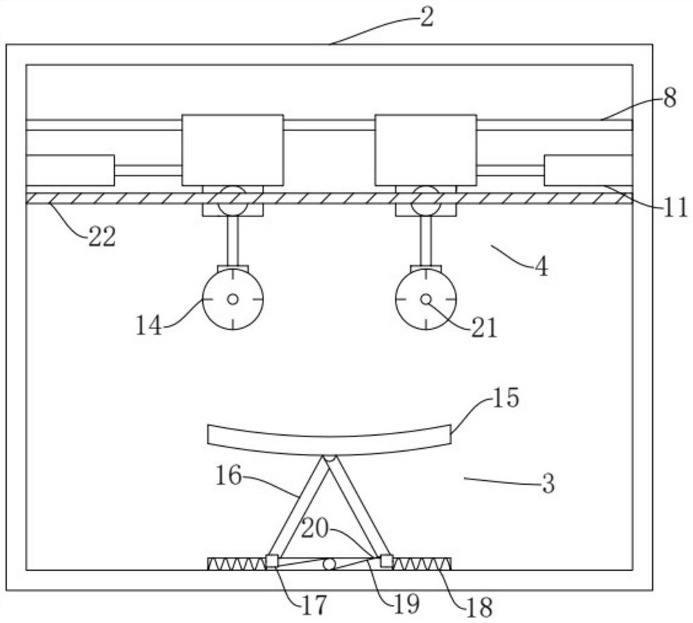
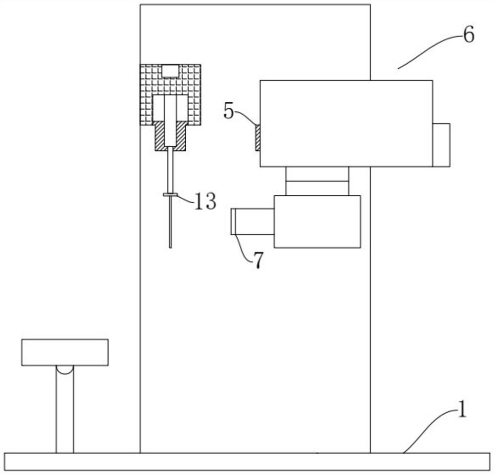
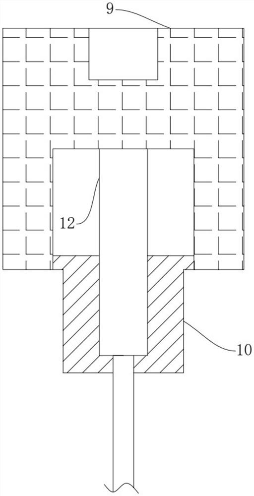
[0017] Such as Figure 1~3 As shown, the technical solution adopted by the present invention is as follows: an intelligent ophthalmic detection...


PUM


Abstract

The invention discloses intelligent detection equipment for ophthalmology department. The intelligent detection equipment comprises a supporting base, a shell, a supporting plate assembly, an eye position adjusting assembly, a photoelectric transmitter, a photoelectric receiver, an ophthalmology detection instrument and a detection observation lens, wherein the detection observation lens is arranged on the ophthalmology detection instrument, and the photoelectric transmitter is arranged on the ophthalmology detection instrument; the photoelectric receiver is arranged on an opening in the front of the shell, the photoelectric receiver and the photoelectric transmitter are correspondingly arranged, the eye position adjusting assembly is arranged between the photoelectric transmitter and the photoelectric receiver, and the eye position adjusting assembly comprises a sliding guide rod, a sliding block, a light blocking block, electric cylinders, an electric telescopic rod, a limiting block and eye position adjusting plates; and the supporting plate assembly comprises a supporting plate, supporting rods, displacement blocks, tension springs, pull ropes, a winch and a displacement guide rail, and luminous sources are arranged on the eye position adjusting plates. The invention belongs to the field of medical detection equipment, and particularly provides the intelligent detection equipment for the ophthalmology department, which can be used for quickly positioning and facilitating detection work of a detection doctor.

Description

technical field [0001] The invention belongs to the field of medical detection equipment, in particular to an ophthalmology intelligent detection equipment. Background technique [0002] Eyes are one of the most important organs of the human body. In order to have a clearer understanding of the eyes, people usually choose to test the eyes in eye medical testing institutions. However, due to the complex structure of the eyes, it is difficult for the detection lens of the detection equipment to be directly at the center of the eye. location, and in the face of collective ophthalmology testing, the testing doctor will often become tired due to too many people testing, and sometimes fall into empiricism during the testing process, making it difficult to make the testing lens right at the center of the human eye, resulting in The results are somewhat skewed. Contents of the invention [0003] In view of the above situation, in order to make up for the above existing defects, t...

Claims


Application Information

Patent Timeline
Patent Type & Authority Applications(China)
IPC IPC(8): A61B3/10A61B3/14
CPCA61B3/10A61B3/14A61B3/0083A61B3/0008
Inventor 罗小凡林伟森牛晓望刘颖李秀秀沈洪锐陈吉林李锴彬叶丽思钟志鹏黄涌黄昕凯邱倩茹
Owner NEUSOFT INST GUANGDONG
Why Eureka
Try Eureka