Stable sand washer for mining machinery

A technology for sand washing machines and mines, applied in the field of sand washing machines, which can solve the problems of inconvenient periodic regulation work, inability to reduce amplitude frequency, and inability to install side-end positions, etc., so as to improve use efficiency, facilitate regulation work, and stabilize processing The effect of production work

Active Publication Date: 2021-09-03
徐州市振武机械厂
View PDF10 Cites 2 Cited by
  • Summary
  • Abstract
  • Description
  • Claims
  • Application Information

AI Technical Summary

Problems solved by technology

[0005] The inner end is not convenient for reciprocating continuous dredging work, and it is not convenient for periodic regulation work. At the same time, there is also the phenomenon that the inner end is not convenient for stable and limited connection, and the installation position of the side end cannot be limited, and the amplitude frequency cannot be reduced. , so a stable sand washing machine for mining machinery is needed to solve the above-mentioned problems

Method used


Image

  • Stable sand washer for mining machinery
  • Stable sand washer for mining machinery
  • Stable sand washer for mining machinery

Examples


Embodiment 1

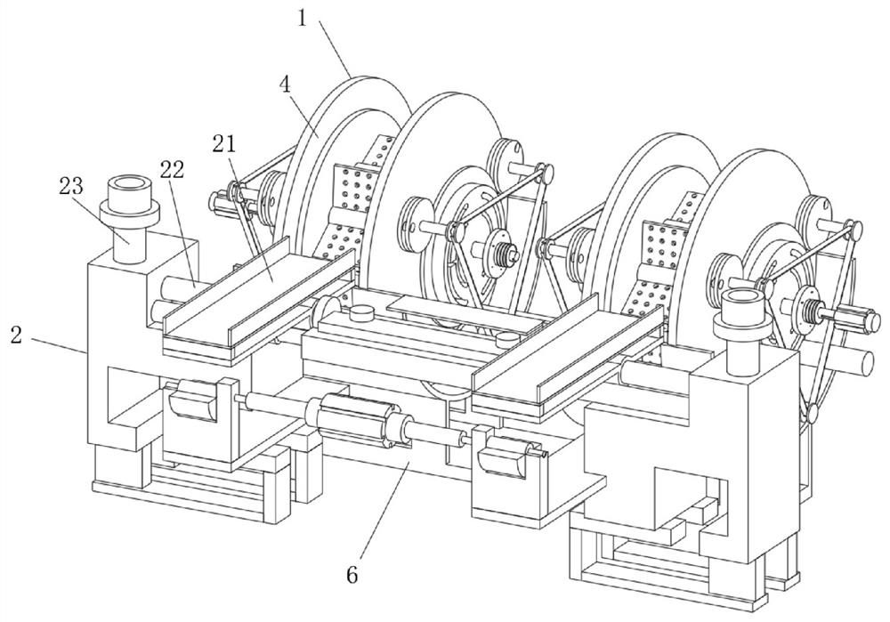
[0033] see Figure 1-7 , an embodiment provided by the present invention: a stable sand washing machine for mining machinery, including a sand washing device 1, the front end of the sand washing device 1 is connected with a conduction device 2, through the sand washing device 1 and the conduction device 2 connection settings can help to carry out the overall construction of the inner end, realize the overall connection production operation, and improve the overall installation and use performance;

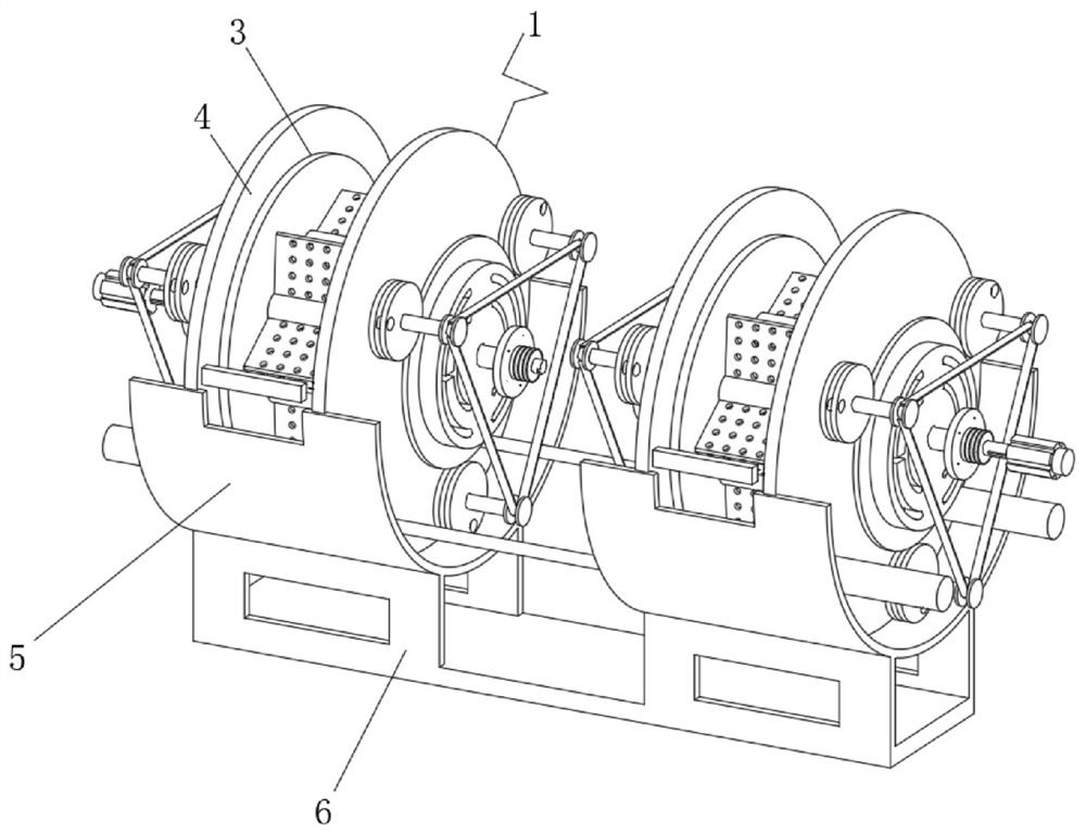
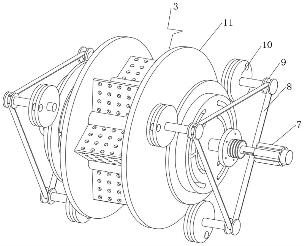
[0034] The sand washing device 1 includes a rotating structure 3, a communication pool 4, an arc-shaped baffle 5 and a base frame 6. The base frame 6 is located at the bottom of the inner end of the sand washing device 1. Fixed connection, the upper end position of the arc-shaped baffle 5 is fixedly connected with the communication pool 4, and the center position of the communication pool 4 is rotatably connected with a rotating structure 3, through the rotating structure 3, the co...

Embodiment 2

[0044] On the basis of Example 1, such as Figure 8 As shown, a water pipe 31 is fixedly connected to the top of the sand washing device 1 , and the water pipe 31 is arranged in communication with the outside world.

[0045] During the implementation of this embodiment, the user can connect the water pipe 31 with the outside world. Through the connection with the outside world, it can help to carry out the internal water intake work, realize the surface sprinkling operation, and help to perform the secondary cleaning work. The sand washing device 1 is discharged to realize reciprocating cleaning work, and the water pipe 31 is arranged on the communication pool 4 to realize the fixed connection of the top position.

[0046] Working principle: The user assembles and sets the sand washing device 1 and the conduction device 2 to realize mutual connection and setting, which helps to carry out the overall construction and setting work. The user first starts the double-head motor 25,...


PUM


Abstract

The invention discloses a stable sand washer for mining machinery. The stable sand washer comprises a sand washing device, wherein the front end position of the sand washing device communicates with a conduction device, the sand washing device comprises a rotating structure, a communication pool, an arc-shaped baffle plate and a base frame; the base frame is arranged at the bottom position of the inner end of the sand washing device, and the upper end of the base frame is fixedly connected with the arc-shaped baffle plate; the upper end position of the arc-shaped baffle plate is fixedly connected with the communication pool; the center position of the communication pool is rotationally connected with a rotating structure; the conduction device comprises a transmission port, a swing frame, a communication groove and a driving component; the driving component is arranged at the bottom of the inner end of the conduction device, the top end of the driving component communicates with the communication groove, the upper end position of the driving component is connected with the transmission port in a swinging manner through the swing frame; and the rotating structure comprises a drive component, a belt, a connecting ring frame, a matching limiting plate and a connecting component. Through the arrangement of the sand washing device, inner end sand washing operation is achieved.

Description

technical field [0001] The invention relates to the technical field of mining machinery, in particular to a stable sand washing machine for mining machinery. Background technique [0002] According to Chinese Patent No. CN202020366186.3, the utility model discloses a stable sand washing machine for mining machinery, which includes a support fixing rod and a placement base. The discharge control plate composed of inserting column, pulling belt, material pulling plate, hollow material plate and through-hole groove is convenient for controlling material conveying. When in use, due to the through-hole groove and inclined The conveying holes of the angle conveying pipe are equal in size, so there will be no obstruction when conveying mine materials, and the shape of the groove of the hollow material plate is equal to the shape of the material pulling plate, so that when it is pulled by the pulling belt, it is effectively To avoid material blockage, when closing, insert the fixed...

Claims


Application Information

Patent Timeline
Patent Type & Authority Applications(China)
IPC IPC(8): B03B5/48
CPCB03B5/48
Inventor 丁计海
Owner 徐州市振武机械厂
Why Eureka
Try Eureka