
Elastic pressing device for antenna processing

An elastic compression and antenna technology, applied in workpiece clamping devices, slot antennas, manufacturing tools, etc., can solve the problems of uneven compression, local overpressure or insufficient pressure, and become longer, and achieve stable clamping force. Effect

Inactive Publication Date: 2021-09-03
BEIJING INST OF RADIO MEASUREMENT
View PDF8 Cites 0 Cited by
  • Summary
  • Abstract
  • Description
  • Claims
  • Application Information

AI Technical Summary

Problems solved by technology

[0005] However, when pressing with a briquetting block, the pressing force remains unchanged throughout the brazing process. With the increase of the brazing temperature, the softening of the structural layer and the solder will easily cause overpressure or insufficient pressure.
Under the condition of overpressure, the heat-expanded material cannot shrink back after cooling, causing the overall structure to become wider, longer, and thinner, and the size is out of tolerance, and the larger the size, the more the tolerance
In the case of insufficient pressure, the weld seam gap is too large, and the liquefied solder cannot completely fill the weld seam, resulting in string waves and leakage waves.
[0006] When elastic clips are used, the compression force of each elastic clip varies with the brazing temperature during the entire brazing process, which cannot be quantitatively measured and evaluated, resulting in uneven compression throughout the entire brazing process, resulting in local overpressure or Insufficient pressure, resulting in local dimension out of tolerance or weld seam not filled with string wave leakage

Method used


Image

  • Elastic pressing device for antenna processing
  • Elastic pressing device for antenna processing
  • Elastic pressing device for antenna processing

Examples


Embodiment 1

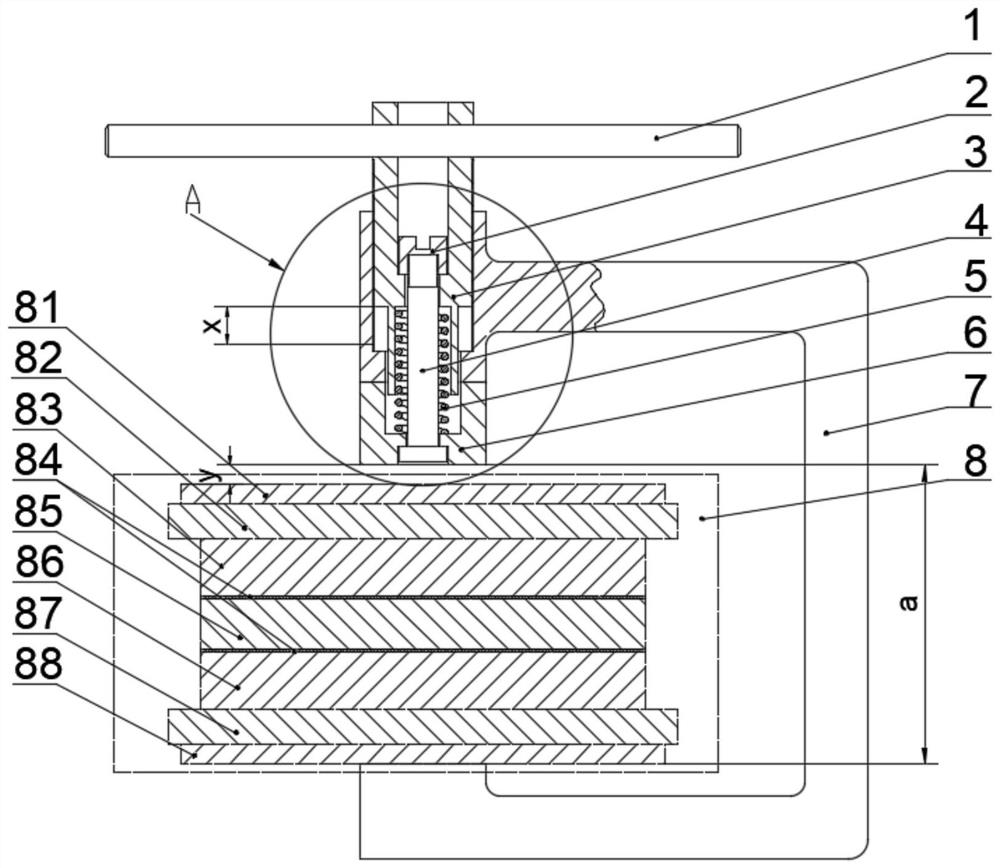
[0040] Such as figure 1 and figure 2 As shown, this embodiment provides an elastic pressing device for antenna processing, including: a C-shaped skeleton 7, an elastic pressing part and an operating part.

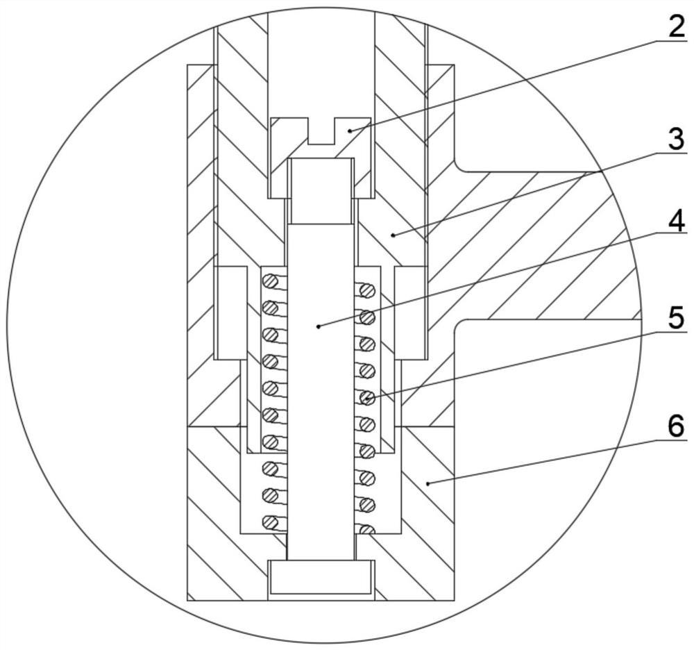
[0041] elastic pressing part, the elastic pressing part is screwed on the top of the C-shaped skeleton 7, the outer side wall of the elastic pressing part is provided with a scale, and the elastic pressing part is determined by the scale The screw-in depth determines the calibration pressure. The operating member is connected to one end of the elastic pressing member, and the operating member drives the elastic pressing member to move up and down.

[0042] Wherein the C-shaped frame 7 forms a clamping shape, so that the workpiece 8 to be welded can be put into the C-shaped frame 7, and the position of the elastic pressing part is changed by manually using the operating part, and the elastic pressing part is moved down to be connected with the welder. The top surface of ...

Embodiment 2

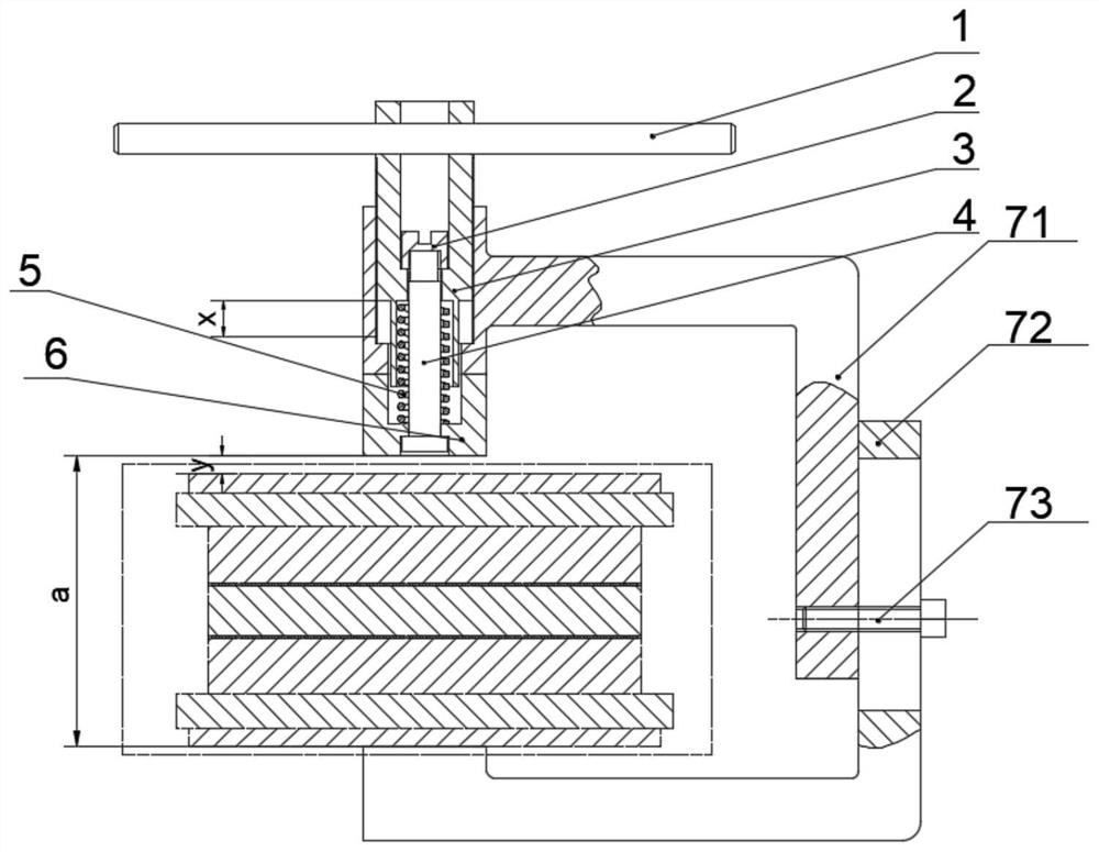
[0067] Such as image 3 As shown, this embodiment provides an elastic pressing device for antenna processing. The difference between this embodiment and Embodiment 1 is that the C-shaped frame 7 includes an upper frame 71 and a lower frame 72, and the upper frame 71 Located vertically above the lower frame 72, one end of the upper frame 71 is set opposite to one end of the lower frame 72 for clamping the workpiece, and the elastic pressing part is slidably connected to the upper frame 71 The other end of the upper frame 71 and the other end of the lower frame 72 are detachably connected. The structure of other parts of this embodiment is exactly the same as that of Embodiment 1.

[0068] Wherein, through the detachable connection of the upper frame 71 and the lower frame 72, the distance between the upper frame 71 and the lower frame 72 can be adjusted, and more workpieces 8 to be welded can be adapted to be clamped.

[0069] Preferably, in this embodiment, the other end of ...


PUM


Abstract

The invention relates to an elastic pressing device for antenna machining, and belongs to the technical field of machining pressing devices. The elastic pressing device comprises a C-shaped framework, an elastic pressing component and an operating part; The elastic pressing component is connected to the top end of the C-shaped framework in a threaded manner, scales are arranged on the outer side wall of the elastic pressing component, and the screwing-in depth of the elastic pressing component is determined through the scales to determine calibration pressure; and the operating part is connected with one end of the elastic pressing component, and the elastic pressing component is driven by the operating part to move up and down. According to the elastic pressing device, by measuring the downward moving distance of the elastic pressing component on the C-shaped framework, the pressure of the elastic pressing component for pressing a to-be-welded workpiece can be quantitatively calculated, so that the clamping pressure of the to-be-welded workpiece is known, and targeted machining is facilitated.

Description

technical field [0001] The invention belongs to the technical field of processing and pressing devices, and in particular relates to an elastic pressing device for antenna processing. Background technique [0002] Compared with other antennas, the aluminum alloy plate slot antenna has the advantages of stable beam pointing, high radiation efficiency, low sidelobe performance, large power capacity, easy amplitude and phase weighting, and high work efficiency. At the same time, it has good strength and Rigidity, light weight, compact structure, high reliability, etc., coupled with its strong anti-interference ability, high precision of radar guidance, and anti-stealth target characteristics, it is widely used in airborne fire control, missile guidance, and target search. , Space-based SAR measurement, etc. [0003] The planar slot antenna is a complex thin-walled cavity structure including radiation, coupling, power division, and excitation waveguide. In the manufacturing pro...

Claims


Application Information

Patent Timeline
Patent Type & Authority Applications(China)
IPC IPC(8): B25B11/00H01Q13/10
CPCB25B11/00H01Q13/10
Inventor 刘守相徐李刚谷征王丹青
Owner BEIJING INST OF RADIO MEASUREMENT
Learn More