
Steel die grabbing mechanism

A technology of grasping mechanism and steel mold, applied in the direction of manipulator, program-controlled manipulator, chuck, etc., can solve the problem of inconvenient adjustment of the position of the steel mold, and achieve the effect of large bearing capacity and precise installation.

Pending Publication Date: 2021-09-03
CHINA RAILWAY CONSTR HEAVY IND
View PDF0 Cites 1 Cited by
  • Summary
  • Abstract
  • Description
  • Claims
  • Application Information

AI Technical Summary

Problems solved by technology

[0004] The purpose of the present invention is to provide a steel mold grabbing mechanism to solve the problem of inconvenient position adjustment during the steel mold installation process

Method used


Image

  • Steel die grabbing mechanism
  • Steel die grabbing mechanism
  • Steel die grabbing mechanism

Examples


Embodiment

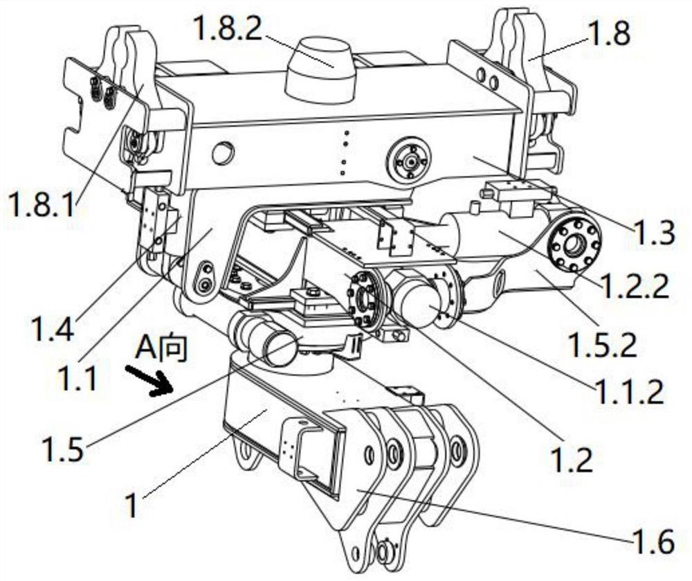
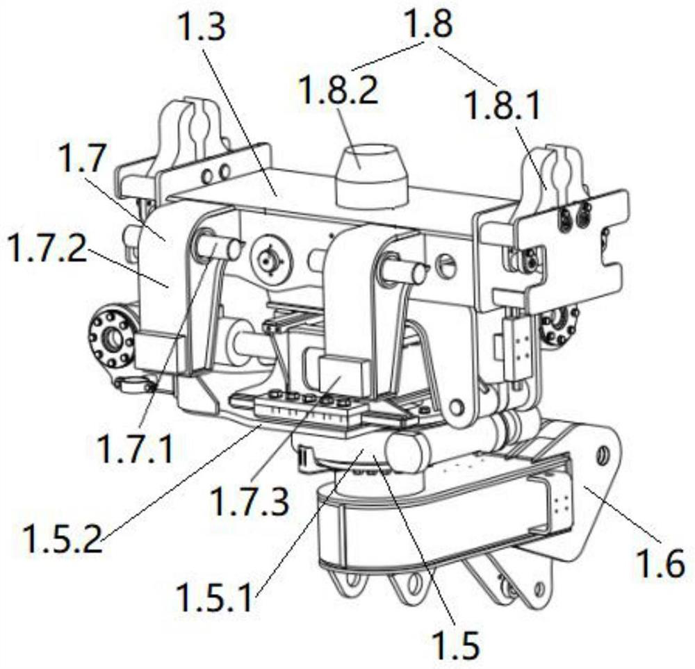
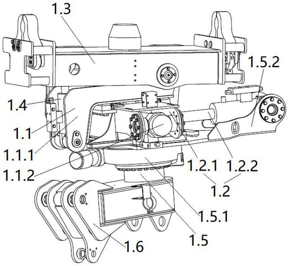
[0038] see Figure 1 to Figure 9 , a steel mold grasping mechanism, this embodiment is applied to the grasping and installation of the prefabricated steel structure (ie steel mold) inside the tunnel.

[0039] A steel mold grasping mechanism, including a detachably connected mechanical gripper 1 and a steel mold connection tool; the mechanical gripper 1 includes a first sliding mechanism 1.1, a second sliding mechanism 1.2 and a The connecting frame 1.3 of the steel mold connecting tool; the connecting frame 1.3 is set on the first sliding mechanism 1.1, the first sliding mechanism 1.1 is set on the second sliding mechanism 1.2, and the second A sliding mechanism 1.1 is perpendicular to the sliding direction of the second sliding mechanism 1.2, and is used to realize the sliding of the connecting frame 1.3 in the front, rear and left and right directions, so as to facilitate the adjustment of the installation position of the steel mold inside the tunnel; the mechanical gripper ...


PUM


Abstract

The invention provides a steel die grabbing mechanism. The steel die grabbing mechanism comprises a mechanical gripper and a steel die connecting tool which are detachably connected; the mechanical gripper comprises a first sliding mechanism, a second sliding mechanism and a connecting frame used for being connected with the steel die connecting tool; the connecting frame is arranged on the first sliding mechanism; the first sliding mechanism is arranged on the second sliding mechanism, and the sliding direction of the first sliding mechanism is perpendicular to that of the second sliding mechanism; the mechanical gripper further comprises a swing mechanism and a rotation mechanism; the swing mechanism is connected between the connecting frame and the first sliding mechanism; and the second sliding mechanism is arranged on the rotation mechanism and used for achieving rotation of the connecting frame in the vertical plane and the horizontal plane. The mechanical gripper has two linear freedom degrees and two rotation freedom degrees, the mounting position of a steel die can be conveniently adjusted in a tunnel, and accurate mounting of the steel die can be achieved.

Description

technical field [0001] The invention relates to the technical field of tunnel construction, in particular to a steel mold grasping mechanism. Background technique [0002] During tunnel excavation, it is necessary to use heavy and bulky steel molds for support, such as plane steel molds and arc steel molds. However, due to the differences in the structure of steel molds and arch frames, the mechanical The gripper is not suitable for grabbing the steel mold; and the mechanical gripper of the traditional arch trolley is connected with multiple booms and telescopic mechanisms to adjust the degree of freedom. When the installation space is narrow, due to the large size of the boom, it is not easy to It is convenient to adjust the installation position of the steel mold through the movement of the boom, which is not conducive to the precise installation of the steel mold. [0003] To sum up, there is an urgent need for a steel mold grasping mechanism to solve the problems in the...

Claims


Application Information

Patent Timeline
Patent Type & Authority Applications(China)
IPC IPC(8): B25J9/00B25J9/04B25J15/08
CPCB25J9/0009B25J9/04B25J15/08
Inventor 黄志坚廖金军刘金书潘国智张裕生刘可可石伟伟
Owner CHINA RAILWAY CONSTR HEAVY IND
Learn More