Manufacturing equipment and method of polystyrene foam plate beam

A technology for polystyrene foam and manufacturing equipment, which is applied to manufacturing equipment and manufacturing fields of polystyrene foam slab beams, can solve problems such as excessive power, increased cost, motor consumption, etc., and achieves energy and cost saving, noise reduction, The effect of saving resources and costs

Pending Publication Date: 2021-09-03
湖南省湘西公路桥梁建设有限公司
View PDF3 Cites 1 Cited by
  • Summary
  • Abstract
  • Description
  • Claims
  • Application Information

AI Technical Summary

Problems solved by technology

[0004] In view of the above-mentioned related technologies, the inventor believes that there is a defect that the motor needs t

Method used


Image

  • Manufacturing equipment and method of polystyrene foam plate beam
  • Manufacturing equipment and method of polystyrene foam plate beam
  • Manufacturing equipment and method of polystyrene foam plate beam

Examples


Embodiment 1

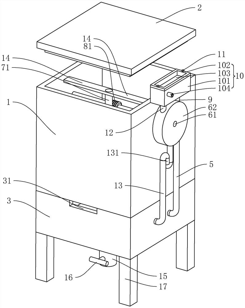
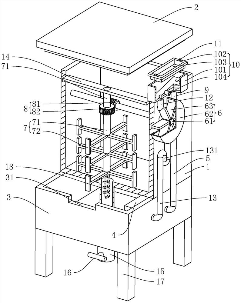
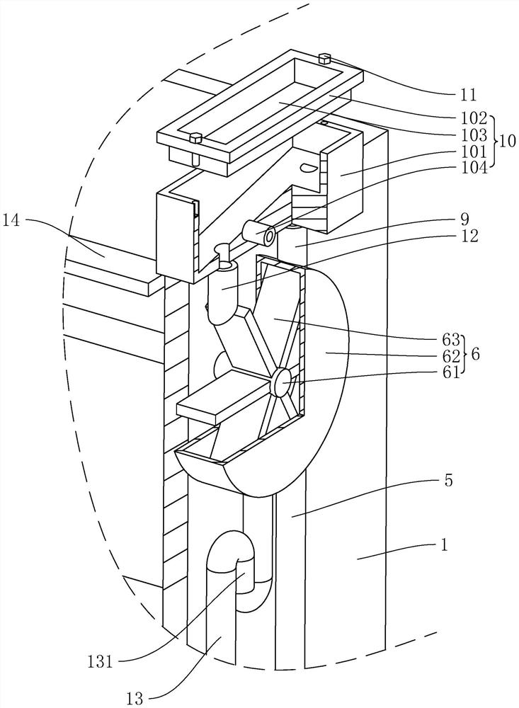
[0043] refer to figure 1 and figure 2, including a melting furnace 1, and a furnace cover 2 is fastened above the melting furnace 1. A heating chamber 3 is arranged at the bottom of the melting furnace 1 , and a water tank 4 is arranged in the heating chamber 3 , and a first steam pipe 5 is connected to the water tank 4 . The first steam pipe 5 extends to the outside of the heating chamber 3 and is connected with a power assembly 6 . A stirring assembly 7 is arranged in the furnace 1 , and a transmission assembly 8 connected with the power assembly 6 is arranged on the stirring assembly 7 . Coal is filled in the heating chamber 3 and ignited, the coal burns to heat the furnace 1, the coal heats the water tank 4, the water in the water tank 4 evaporates into steam, and the steam enters the first steam pipe 5, and the power assembly 6 converts the first steam pipe 5 The steam in the furnace is converted into mechanical energy, and the mechanical energy is transmitted to the s...

Embodiment 2

[0063] refer to Figure 4 , a kind of manufacturing method of polystyrene foam board girder, comprises the following steps:

[0064] S100. Open the cover plate 102 and inject water into the cooling box 101;

[0065] S200. Fasten the cover plate 102, use the fixing bolt 11 to pass through and thread-connect the cooling box 101, and fix the cover plate 102 and the cooling box 101;

[0066] S300. Put coal in the heating chamber 3 through the ventilation groove 31;

[0067] S301. Light the coal in the heating chamber 3 through the ventilation slot 31;

[0068] S400. Pour polystyrene resin and polymer into the melting furnace 1;

[0069] S500. After the material in the furnace 1 reaches the standard, place the mold under the discharge pipe 15, and open the valve 16; close the valve 16 after the mold is full.


PUM


Abstract

The invention relates to manufacturing equipment and method of a polystyrene foam plate beam, and belongs to the field of polystyrene foam manufacturing. The manufacturing equipment comprises a smelting furnace, a furnace cover is buckled on the smelting furnace, a heating chamber is arranged at the bottom of the smelting furnace, a water tank is arranged in the heating chamber, the water tank communicates with a first steam pipe, and the first steam pipe extends to the outside of the heating chamber; a power assembly is arranged on one side of the smelting furnace, the power assembly comprises a shell, a transverse shaft and blades, the transverse shaft is rotationally connected into the smelting furnace, the transverse shaft penetrates through and is rotationally connected to the shell, the blades are located in the shell and connected to the transverse shaft, and the multiple blades are arranged along the circumference of the transverse shaft; the first steam pipe communicates with the bottom of the shell, and the first steam pipe is positioned obliquely below the transverse shaft; the upper side of the shell communicates with the outside; a stirring assembly is arranged in the smelting furnace, and a transmission assembly connected with the stirring assembly is arranged on the transverse shaft. The equipment and the method have the effect of saving the cost.

Description

technical field [0001] The present application relates to the field of polystyrene foam manufacturing, in particular to a polystyrene foam slab beam manufacturing equipment and a manufacturing method thereof. Background technique [0002] At present, in the field of construction, the internal formwork of hollow slab girder is an important component in bridge construction. Because polystyrene foam has very good heat insulation, extremely low water absorption, high compression resistance and high anti-aging properties, part of the inner mold of the hollow slab girder is made of polystyrene foam. [0003] In the related art, the melting furnace and the furnace cover are included, and the polystyrene resin and the polymer are poured into the melting furnace, and the two are heated. A stirring rod is arranged inside the melting furnace, and a motor connected with the stirring rod is arranged outside the melting furnace. Start the motor to drive the stirring rod to mix the mater...

Claims


Application Information

Patent Timeline
IPC IPC(8): B29B7/16B29B7/22B29B7/82B29C39/02B29C39/22
CPCB29B7/22B29B7/16B29B7/826B29C39/22B29C39/02
Inventor 李成勇向俊霖刘继元周鹏谢开航
Owner 湖南省湘西公路桥梁建设有限公司
Why Eureka
Try Eureka