Fiber winding device

A winding device and fiber technology, applied in the field of fiber winding, can solve the problems of local stress concentration, uneven winding, low winding efficiency, etc., achieve the effect of reducing the use of fibers, improving the winding effect, and ensuring the winding efficiency

Active Publication Date: 2021-09-03
TAIYUAN UNIV OF TECH
View PDF13 Cites 3 Cited by
  • Summary
  • Abstract
  • Description
  • Claims
  • Application Information

AI Technical Summary

Problems solved by technology

At present, in the hoop winding process, single-bundle fiber hoop winding is mainly used. The winding efficiency of this process is low, and the current process cannot achieve continuous production, and there is manual intervention in the entire winding process.
[0005] The size of the inner liner of the pressure vessel is diversified, but the size of the inner liner that meets the multi-bundle fiber synchronous winding process is relatively single, which brings great limitations to the process
In the current multi-bundle fiber winding, multiple bundles of fibers (fiber number ≤ 5) are gathered into a large tow for winding, but the essence is still single-bundle winding; and during the winding process, it will cause fiber stacking, uneven winding, and winding process Medium fiber slippage, local stress concentration
At the same time, the degree of automation of single-bundle filament winding is low and the production efficiency is low

Method used


Image

  • Fiber winding device
  • Fiber winding device
  • Fiber winding device

Examples


Embodiment Construction

[0078] The following clearly and completely describes the technical solutions in the embodiments of the present invention. Obviously, the described embodiments are only some of the embodiments of the present invention, but not all of them. Based on the embodiments of the present invention, all other embodiments obtained by persons of ordinary skill in the art without making creative efforts belong to the protection scope of the present invention.

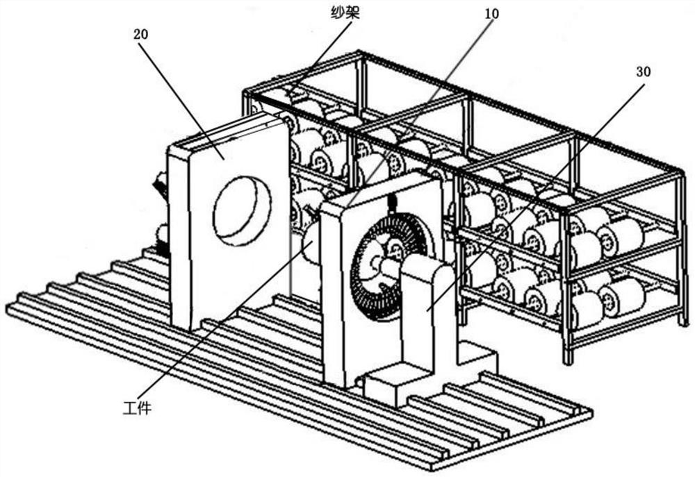
[0079] Such as Figures 1 to 24 As shown, a fiber winding device includes a helical winding device 10, a hoop winding device 20 and a fixing device 30. The fixing device 30 clamps the workpiece and drives the workpiece to rotate radially and move axially. The helical winding device 10 pairs The workpiece on the fixing device 30 is spirally wound; the workpiece on the fixing device 30 is hoop wound by the hoop winding device 20;

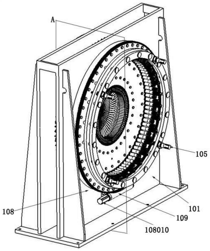
[0080] The spiral winding device 10 includes a frame body 101 and a guide wire head 102, the frame body...


PUM


Abstract

The invention belongs to the technical field of fiber winding, and particularly relates to a fiber winding device. The device comprises a spiral winding device, an annular winding device and a fixing device, a workpiece is clamped through the fixing device and driven to rotate in the radial direction and move in the axial direction, and spiral winding is conducted through the spiral winding device; annular winding is conducted through the annular winding device; the spiral winding device comprises a frame body and a plurality of silk guide heads, a second through hole is formed in the frame body, the plurality of silk guide heads are annularly distributed along the center of the second through hole and are rotationally connected with the frame body, and fibers can extend out of each silk guide head; a first driving mechanism is arranged on the frame body, and each silk guide head is driven to rotate through the first driving mechanism; and the annular winding mechanism comprises a rack, a fixing plate, a fiber bundle cylinder, a bundling device and a silk guiding piece, the fixing plate is rotationally connected with the rack, the fixing plate is connected with a driving element, and the fixing plate is driven to rotate through the driving element. Through the device, the winding efficiency and the winding quality can be improved.

Description

technical field [0001] The invention belongs to the technical field of fiber winding, and in particular relates to a fiber winding device. Background technique [0002] After years of development, pressure vessels have been widely used in aerospace, medical and health, and daily life; with the continuous emergence of new materials and new processes, pressure vessels are developing towards lightweight and high strength. In the future, it will be developed towards a type IV container with a plastic inner liner and a fiber-wound outer surface as a reinforcement layer. The working pressure of Type IV container is higher, and because the fiber layer is used as the main pressure-bearing layer, the safety performance is higher. In different application fields, the size of the container is also different, which puts forward higher requirements for the versatility of the winding equipment. [0003] Filament winding is one of the important links in the pressure vessel forming proces...

Claims


Application Information

Patent Timeline
Patent Type & Authority Applications(China)
IPC IPC(8): B29C53/58B29C53/80
CPCB29C53/58B29C53/8008B29C53/8016B29L2031/7156B29C53/602B29C53/64
Inventor 梁建国赵晓冬刘江林李辉郭俊杰赵润田
Owner TAIYUAN UNIV OF TECH
Why Eureka
Try Eureka