Lifting frame and construction method thereof

A lifting frame and lifter technology, which is applied to lifting frames, lifting devices, etc., can solve the problems of lifting fulcrum, large amount of measures, low construction safety, etc., and achieve the effect of reducing the amount of measures and improving convenience

Active Publication Date: 2021-09-03
中建科工集团武汉有限公司
View PDF4 Cites 0 Cited by
  • Summary
  • Abstract
  • Description
  • Claims
  • Application Information

AI Technical Summary

Problems solved by technology

However, when the rods in the top area of ​​the column are relatively dense, it is impossible to use steel beams, steel columns or concrete structures as the lifting fulcrum, and the measures to build a temporary lifting frame are large, the economy is poor, and the construction safety is low

Method used


Image

  • Lifting frame and construction method thereof
  • Lifting frame and construction method thereof
  • Lifting frame and construction method thereof

Examples


Embodiment Construction

[0032] Embodiments of the present invention are described in detail below, examples of which are shown in the drawings, wherein the same or similar reference numerals designate the same or similar elements or elements having the same or similar functions throughout. The embodiments described below by referring to the figures are exemplary only for explaining the present invention and should not be construed as limiting the present invention.

[0033] In the description of the present invention, it should be understood that the orientation descriptions, such as up, down, front, back, left, right, etc. indicated orientations or positional relationships are based on the orientations or positional relationships shown in the drawings, and are only In order to facilitate the description of the present invention and simplify the description, it does not indicate or imply that the device or element referred to must have a specific orientation, be constructed and operated in a specific ...


PUM


Abstract

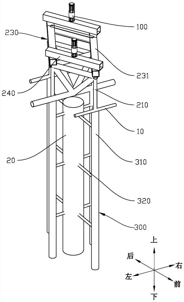
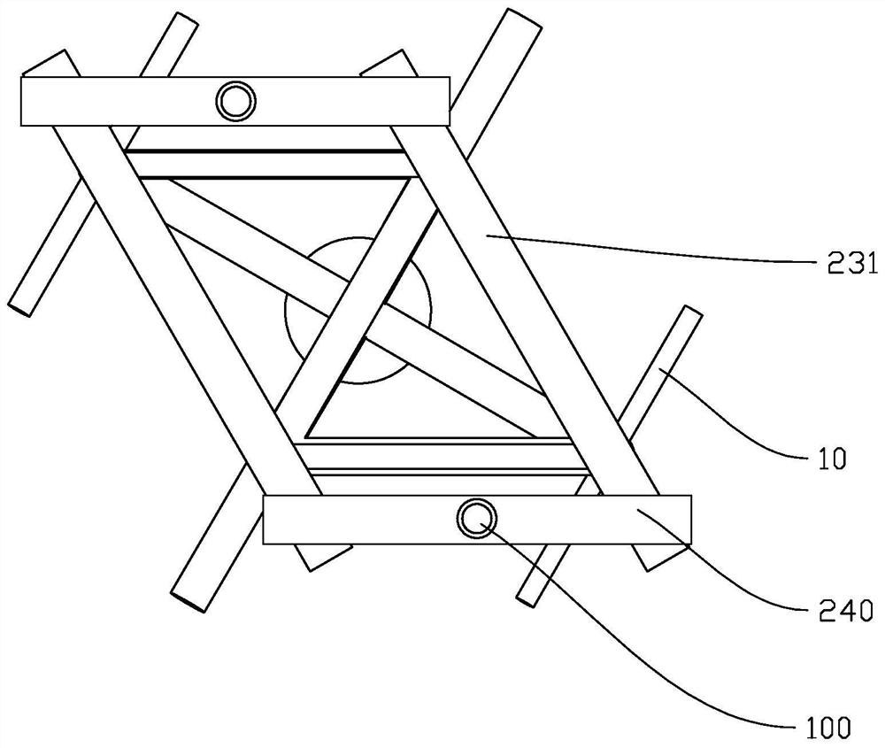
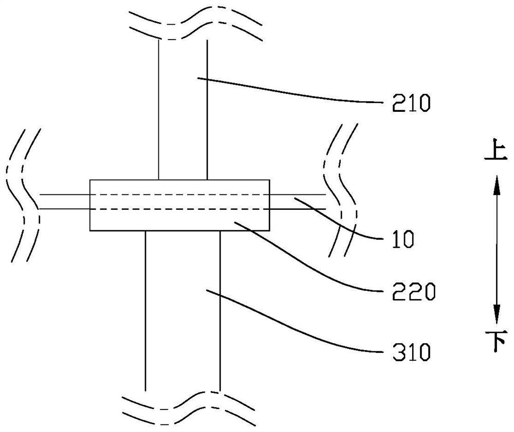
The invention discloses a lifting frame and a construction method thereof. The lifting frame comprises a plurality of lifters, transfer joints and a frame body, wherein, the lifters are used for lifting a steel structure; the transfer joints comprise a plurality of connecting columns, the connecting columns are connected with the lifters and located above web members of the steel structure, and the web members can support the connecting columns; the frame body comprises a plurality of supporting columns, the top ends of the supporting columns are located below the web members, the supporting columns are used for supporting the web members, and the frame body is used for being connected with steel beams or concrete members of the steel structure; and member bars in a column top area in the steel structure are dense, the operation space is small, and a temporary support with a large measure quantity cannot be built. According to the lifting frame and the construction method thereof in the embodiment of the invention, the web members in an existing steel structure can be fully utilized as the transfer joints for pressure transmission, the measure quantity in the member bar dense area is small, and the construction convenience is improved.

Description

technical field [0001] The invention relates to the construction field, in particular to a lifting frame and a construction method thereof. Background technique [0002] At present, during the construction of long-span steel structure buildings, many structures of steel structure buildings are constructed by the lifting method. Generally, the steel beams, steel columns or concrete structures that have been constructed in the existing steel structure are used as the lifting fulcrum for lifting, and some construction methods use temporary lifting frames as the lifting fulcrum for lifting. However, when the rods in the column top area are relatively dense, steel beams, steel columns or concrete structures cannot be used as lifting fulcrums, and the measures to build a temporary lifting frame are large, the economy is poor, and the construction safety is low. Contents of the invention [0003] The present invention aims to solve at least one of the technical problems existing...

Claims


Application Information

Patent Timeline
Patent Type & Authority Applications(China)
IPC IPC(8): B66F7/02B66F7/28
CPCB66F7/02B66F7/28
Inventor 黎健戴维陈恩张勇亮程文豪刘传钦
Owner 中建科工集团武汉有限公司
Why Eureka
Try Eureka