Safe jacking method and equipment for high-rise steel structure installation
A technology for steel structure and installation, which is applied in the direction of lifting frame, lifting device, building structure, etc., can solve the problems of easy falling of components, major safety hazards, and can not bear the limit of components, and achieves the effect of stable lifting operation.
- Summary
- Abstract
- Description
- Claims
- Application Information
AI Technical Summary
Problems solved by technology
Method used
Image
Examples
Embodiment 1
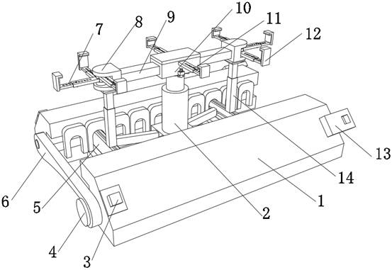
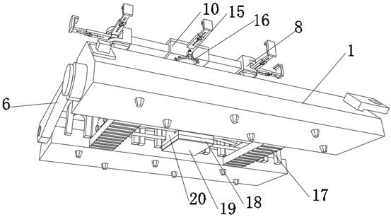
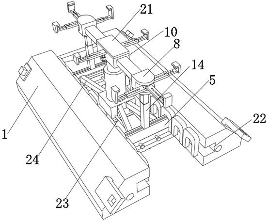
[0037] A safe jacking method for high-rise steel structure installation, such as Figure 1-6 shown, including the following steps:
[0038] S1: Transport the safety jacking equipment to the construction site and adjust the orientation. According to the lateral distance between the place where the construction profiles are placed and the installation place of the high-rise steel structure, fix the extension part on the safety jacking equipment to increase the movement of the safety jacking equipment scope;
[0039] S2: According to the size of the steel structure profile to be lifted, use the spacing adjustment part to adjust the support distance on the safety jacking equipment;
[0040] S3: Fix the steel structure profile on the clamping part of the safety jacking device;
[0041] S4: Start the lifting part on the safety lifting equipment to lift and transport the steel structure profiles.
Embodiment 2
[0043] A kind of safe jacking method for high-rise steel structure installation described in embodiment 1, such as Figure 1-5 As shown, in order to improve the stability of the jacking operation; the safe jacking method needs to be realized by a safe jacking device, and the safe jacking device includes two bases 1 and a supporting structure, and the two bases 1 The structure is basically the same, the inner wall of one side of the base 1 is provided with a moving rail 22, the outer wall of the base 1 close to the moving rail 22 is connected with a plurality of U-shaped pieces 30 through hinges, and the outer wall of the side of the U-shaped piece 30 near the bottom end passes through Bolts are fixed with iron blocks 26, and the outer wall of the base 1 near the moving rail 22 is fixed with magnets 28 by bolts, and the quantity of the magnets 28 is the same as that of the iron blocks 26; a prism 29; the support structure includes two support seats 5 and a top support seat 34 t...
PUM
 Abstract
Description
Claims
Application Information
 - R&D
- Intellectual Property
- Life Sciences
- Materials
- Tech Scout
- Unparalleled Data Quality
- Higher Quality Content
- 60% Fewer Hallucinations
Browse by: Latest US Patents, China's latest patents, Technical Efficacy Thesaurus, Application Domain, Technology Topic, Popular Technical Reports.
© 2025 PatSnap. All rights reserved.Legal|Privacy policy|Modern Slavery Act Transparency Statement|Sitemap|About US| Contact US: help@patsnap.com


