Dielectric resonator antenna and communication equipment

A dielectric resonator and antenna technology, applied in resonant antennas, antennas, electrical short antennas, etc., can solve the problems of complex dielectric substrate layer structure, non-integrated dual-frequency implementation methods, etc., to increase the frequency band coverage and simplify the structure. Effect

Pending Publication Date: 2021-09-03
SHENZHEN SUNWAY COMM
View PDF0 Cites 0 Cited by
  • Summary
  • Abstract
  • Description
  • Claims
  • Application Information

AI Technical Summary

Problems solved by technology

However, the design based on the patch antenna has disadvantages such as the need for a complex dielectric substrate layer structure and non-integrated dual-band implementation. Therefore, the current application of 5G millimeter wave broadband or multi-band antennas faces many design challenges.

Method used


Image

  • Dielectric resonator antenna and communication equipment
  • Dielectric resonator antenna and communication equipment
  • Dielectric resonator antenna and communication equipment

Examples


Embodiment 1

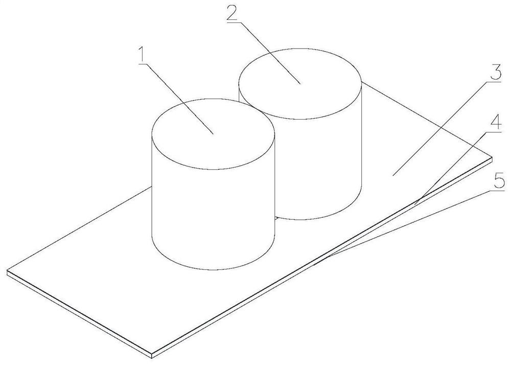
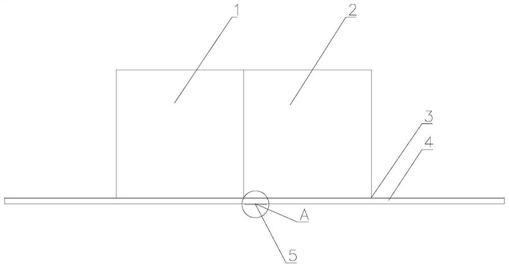
[0055] Please refer to Figure 1 to Figure 3 , a dielectric resonator antenna, comprising a first dielectric block 1, a second dielectric block 2, a metal layer 3, a dielectric layer 4 and a microstrip 5; wherein, the first dielectric block 1 and the second dielectric block 2 Can be in shapes such as rectangles, circles and polygons;

[0056] One side of the metal layer 3 is provided with the dielectric layer 4; the first dielectric block 1 and the second dielectric block 2 are provided on the other side of the metal layer 3; the first metal layer 3. Two feeding slots 6 are provided at positions corresponding to the first dielectric block 1 and the second dielectric block 2;

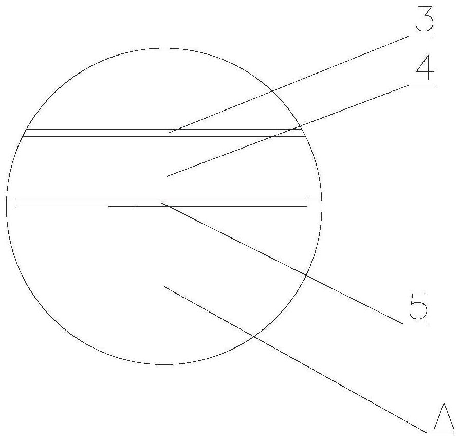
[0057] Please refer to Figure 4 , the microstrip 5 is arranged on the side of the dielectric layer 4 away from the metal layer 3, and is located between the two feeding slots 6;

[0058] Specifically, in an optional embodiment, the first dielectric block 1 and the second dielectric block 2 are cylind...

Embodiment 2

[0076] The difference between this embodiment and the first embodiment is that it also includes a rectangular feeding slot 7;

[0077] Please refer to Figure 10 , the first metal layer 3 is also provided with a rectangular feeding slot 7; the rectangular feeding slot 7 is distributed on both sides of the two feeding slots 6;

[0078] Specifically, the rectangular feeding slots 7 include four groups; two groups of the rectangular feeding slots 7 are respectively provided on both sides of the two feeding slots 6, and two groups of the rectangular feeding slots 7 are set On the position corresponding to the first dielectric block 1 on the metal layer 3, another two groups of the rectangular feed slots 7 are arranged on the position corresponding to the second dielectric block 2 on the metal layer 3 .

Embodiment 3

[0080] A communication device includes the dielectric resonator antenna described in Embodiment 1 or Embodiment 2.

[0081] In summary, the present invention provides a dielectric resonator antenna and a communication device, by disposing the dielectric layer on one side of the metal layer, and disposing the first dielectric block and the second dielectric block on the other side of the metal layer , and the metal layer is provided with two feeding slots and four sets of rectangular feeding slots; the two dielectric blocks are excited to radiate in different modes through the two feeding slots, and the two feeding slots are connected to the first dielectric block. Or the second dielectric block forms the first mode resonance, the two feeding slots and the rectangular space formed by the first dielectric block and the second dielectric block form the second mode resonance, and the two feeding slots themselves also form the third mode resonance, Realize three modes of resonance ...


PUM

PropertyMeasurementUnit
radiusaaaaaaaaaa
heightaaaaaaaaaa

Abstract

The invention discloses a dielectric resonator antenna and communication equipment. A dielectric layer is arranged on one side of a metal layer, a first dielectric block and a second dielectric block are arranged on the other side of the metal layer, and the metal layer is provided with two feed slots. The two dielectric blocks are excited by the two feed slots to radiate in different modes, so that the two feed slots and the first dielectric block or the second dielectric block form first mode resonance, the two feed slots and a rectangular space formed by the first dielectric block and the second dielectric block form second mode resonance, and the two feed slots form third mode resonance, so that three modes of resonance can be generated through the double slots and the two dielectric blocks, the frequency band coverage rate of an antenna module is greatly increased, and the structure of the antenna module is simplified by adopting a design mode based on a dielectric resonator antenna.

Description

technical field [0001] The invention relates to the technical field of antennas, in particular to a dielectric resonator antenna and communication equipment. Background technique [0002] 5G is the research and development focus of the global industry, and the development of 5G technology and the formulation of 5G standards have become the consensus of the industry. With the development of 5G technology, the requirements for 5G antenna modules are getting higher and higher. In particular, the performance requirements for covering multiple frequency bands are getting higher and higher. In order to realize that the 5G antenna module can cover multiple frequency bands, it is easy to think of using multiple antennas in different frequency bands to form a multi-antenna module. However, the multi-antenna module will inevitably increase the space occupied by the antenna device in the terminal device. [0003] In this regard, in the prior art, a design based on a broadband or mul...

Claims


Application Information

Patent Timeline
Patent Type & Authority Applications(China)
IPC IPC(8): H01Q9/04H01Q1/38H01Q1/50H01Q5/10H01Q5/28H01Q5/50H01Q1/24
CPCH01Q9/0485H01Q1/38H01Q1/50H01Q5/10H01Q5/28H01Q5/50H01Q1/242
Inventor 赵伟侯张聚唐小兰戴令亮谢昱乾
Owner SHENZHEN SUNWAY COMM
Why Eureka
Try Eureka