Eureka AIR delivers breakthrough ideas for toughest innovation challenges, trusted by R&D personnel around the world.

Storage battery module

A battery module and battery technology, applied in the direction of lithium batteries, non-aqueous electrolyte batteries, secondary batteries, etc., can solve the problems of abnormal battery change, melting, overheating, etc.

Pending Publication Date: 2021-09-03
PANASONIC INTELLECTUAL PROPERTY MANAGEMENT CO LTD
View PDF14 Cites 0 Cited by
  • Summary
  • Abstract
  • Description
  • Claims
  • Application Information

AI Technical Summary

Problems solved by technology

On the other hand, if the battery is placed under abnormal conditions and high-temperature flammable gas is emitted from the inside, the frame of the battery pack containing the battery may be damaged, melted, overheated, or the emitted flammable gas may Gas leaks to the outside of the battery pack
Furthermore, due to the heat emitted by the combustible gas, the temperature of adjacent batteries becomes high one by one, and all the batteries inside the battery pack become abnormal, or the frame of the battery pack melts due to heat.

Method used


Image

  • Storage battery module
  • Storage battery module
  • Storage battery module

Examples


Embodiment 1

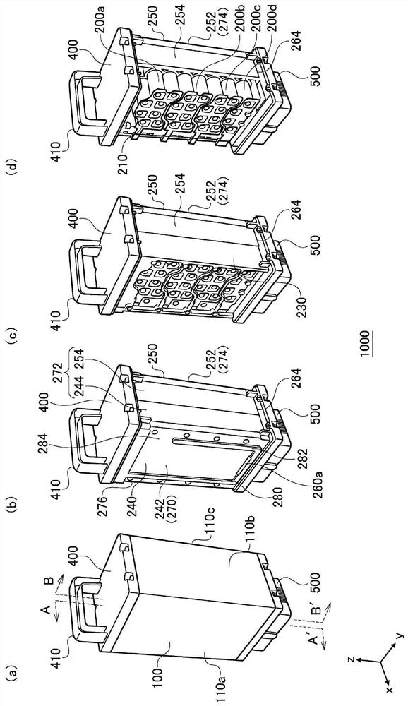
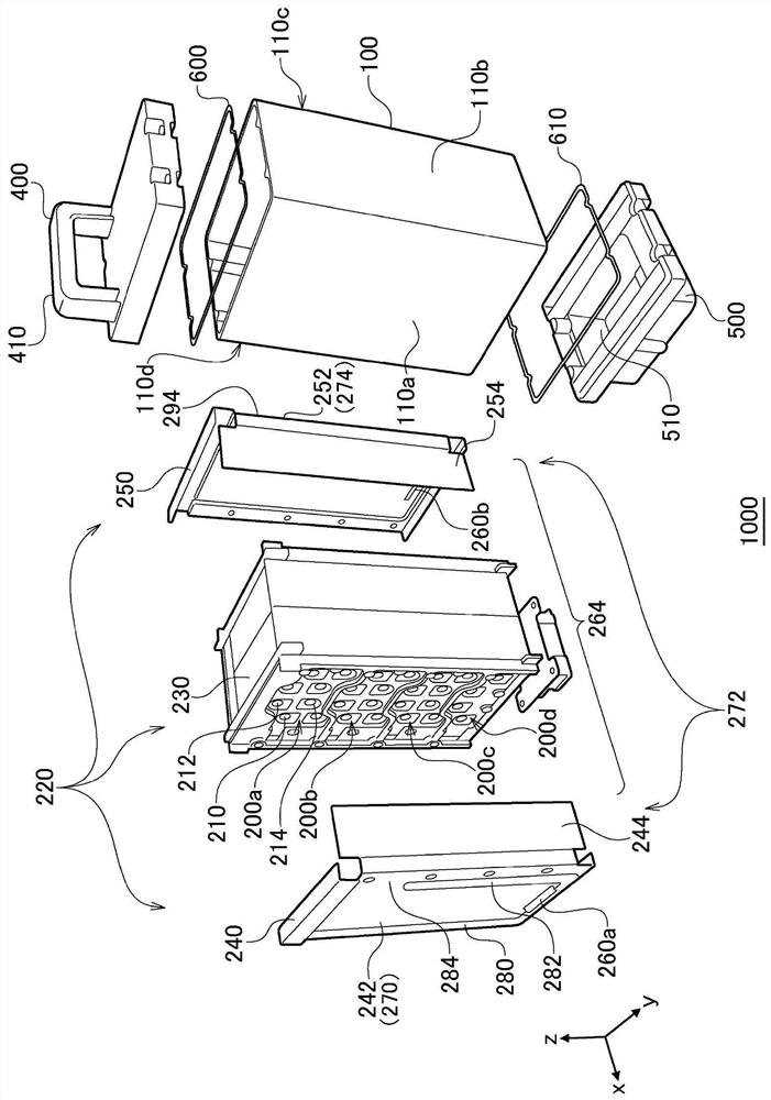
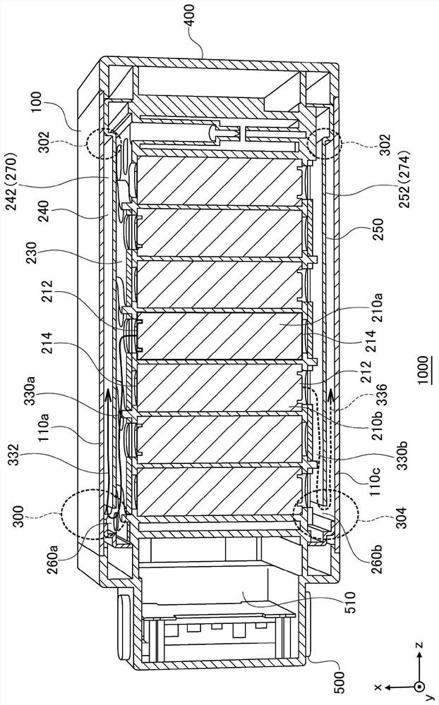
[0022] Before concretely describing the embodiments of the present disclosure, the outline of Embodiment 1 will be described. This embodiment relates to a battery module that accommodates a plurality of battery cells. When each battery cell is a lithium ion secondary battery, gas is generated in the battery cell when an internal short circuit or the like occurs. Also, the pressure inside the battery cell increases due to gas generation, but the gas is released from the positive electrode side to the outside of the battery cell through the safety mechanism. Such gas has high temperature and high pressure, and if combustion by the gas occurs, other battery cells in the battery module will also run away thermally (burning spread). Due to this burning, the entire battery module or the entire product may burn. In order to suppress the spread of combustion by gas, for example, it is effective to provide an exhaust port in the battery module and to release the gas from the exhaust ...

Embodiment 2

[0052] Next, Example 2 will be described. Example 2, like Example 1, relates to a battery module that accommodates a plurality of battery cells. In Example 1, the first exhaust path and the second exhaust path are formed using different surfaces of the inner case. On the other hand, the second embodiment arranges the middle case between the outer case and the inner case, the space between the inner case and the middle case forms the first exhaust path, and the space between the middle case and the outer case The space between forms the second exhaust path. Hereinafter, the difference from Example 1 will be mainly explained.

[0053] Figure 6 (a)-(b) are perspective views showing the structure of the battery module 2000 . Figure 6 (a) is a perspective view showing the appearance of the battery module 2000, Figure 6 (b) is the perspective view which looked at the battery module 2000 from the lower side. The battery module 2000 includes an outer case 2100 and a lower cas...

Embodiment 3

[0068] Next, Example 3 will be described. The third embodiment relates to a battery module that accommodates a plurality of battery cells in the same manner as described above. In Examples 1 and 2, a metal outer case is disposed on the outermost side of the battery module. In Example 3, a resin cover is arranged on the outside of the outer case for the purpose of increasing the degree of freedom of the mounting structure of the battery module charger or load device and increasing the designability of the battery module. Hereinafter, the difference from Example 1 will be mainly explained.

[0069] Figure 9 (a)-(d) are perspective views showing the structure of the battery module 3000 . exist Figure 9 In (a)-(d), the same orthogonal coordinate system as above is specified. Figure 9 (a) shows the appearance of the battery module 3000 . The battery module 3000 includes a resin cover 3700 . The resin cover 3700 is formed of resin, and has a vertically elongated box shape ...


PUM


Abstract

An inner case 220 accommodates a plurality of storage battery cells 210. An outer case 100 accommodates the inner case 220. A first inner exhaust port 260a is provided in the inner case 220, and an outer exhaust port is provided in a lower case 500. A first exhaust pathway from a first position in the first inner exhaust port 260a to a second position, and a second exhaust pathway from the second position to a third position in the outer exhaust port are provided in a space between the inner case 220 and the outer case 100.

Description

technical field [0001] The present disclosure relates to battery modules, and more particularly to battery modules housing a plurality of battery cells. Background technique [0002] Looking for a battery pack with high capacity, high voltage, high output and high safety. On the other hand, if the battery is placed under abnormal conditions and high-temperature flammable gas is emitted from the inside, the frame of the battery pack containing the battery may be damaged, melted, overheated, or the emitted flammable gas may Gas leaks to the outside of the battery pack. Furthermore, due to the heat emitted by the combustible gas, the temperature of adjacent batteries becomes high one by one, and all the batteries in the battery pack become abnormal, or the casing of the battery pack is melted by heat. In order to prevent this, the battery pack is provided with an opening for releasing the flammable gas to the outside (for example, refer to Patent Document 1). [0003] [Prior...

Claims


Application Information

Patent Timeline
Patent Type & Authority Applications(China)
IPC IPC(8): H01M50/204H01M50/35H01M50/213
CPCY02E60/10H01M50/213H01M50/107H01M50/284H01M50/367H01M10/443H01M10/052
Inventor 远矢正一中岛武董泽海
Owner PANASONIC INTELLECTUAL PROPERTY MANAGEMENT CO LTD
Why Eureka
Eureka Blog
Learn More