Eureka AIR delivers breakthrough ideas for toughest innovation challenges, trusted by R&D personnel around the world.

Projection display device

A technology for a display device and a light source device, which is applied to projection devices, televisions, optics, etc., can solve the problems of lamp replacement and the inability of users to proceed smoothly.

Inactive Publication Date: 2012-07-04
SANYO ELECTRIC CO LTD
View PDF5 Cites 0 Cited by
  • Summary
  • Abstract
  • Description
  • Claims
  • Application Information

AI Technical Summary

Problems solved by technology

In this way, the user may not be able to replace the lamp smoothly due to the glare of the emitted light.

Method used


Image

  • Projection display device
  • Projection display device
  • Projection display device

Examples


change example 1

[0119] Figure 10 It is a figure for demonstrating the projector which concerns on the modification 1. Figure 10 (a) is a diagram showing the processing procedure of the lamp control processing, Figure 10 (b) is a figure which shows an example of the state change of each lamp unit 300 when performing a lamp control process.

[0120] In this modified example, when the control part 501 determines that any lamp cover 7 is open (101: YES), it turns off only the lamp unit 300 facing the corresponding lamp unit 300 (S104). For example, if Figure 10 As shown in (b), when the lamp cover 7 corresponding to the RB lamp unit 300d at the rear right is opened, the LB lamp unit 300c at the rear left is turned off.

[0121] Leaked light from the opposing lamp unit 300 enters the lamp housing portion 212 most easily. Therefore, if the structure in which the opposing lamp units 300 are turned off as in this modified example is adopted, compared with the above-mentioned embodiment, altho...

change example 2

[0123] Figure 11 It is a figure for demonstrating the projector which concerns on the modification 2. Figure 11 (a) is a diagram showing the processing procedure of the lamp control processing, Figure 11 (b) is a figure which shows an example of the state change of each lamp unit 300 when performing a lamp control process.

[0124]In this modified example, when the control unit 501 determines that a certain lamp cover 7 is open (S101: YES), only the lamp unit 300 adjacent to the lamp unit 300 facing the corresponding lamp unit 300 is turned off (S105). ). For example, if Figure 11 As shown in (b), when the lamp cover 7 corresponding to the RB lamp unit 300d at the rear right is opened, the LF lamp unit 300a at the front left is turned off.

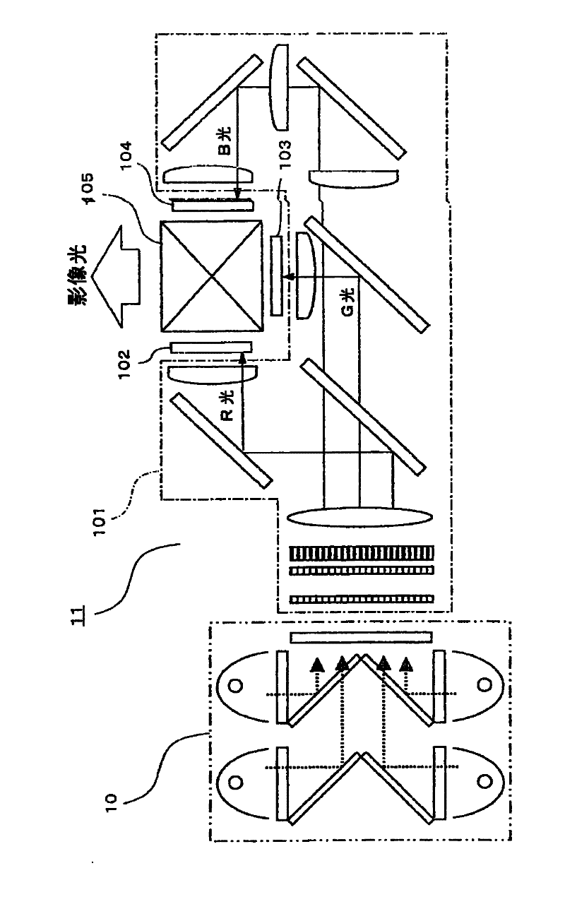
[0125] As mentioned above, the optical system 11 includes a dichroic mirror and liquid crystal panels 102 , 103 , 104 . The incident angles to the dichroic mirror are different between the light from the right LF lamp unit 300a an...

change example 3

[0130] Figure 12 It is a figure for demonstrating the projector which concerns on the modification 3. Figure 12 (a) is a diagram showing the processing procedure of the lamp control processing, Figure 12 (b) is a figure which shows an example of the state change of each lamp unit 300 when performing a lamp control process.

[0131] In this modified example, when it is determined that a certain lamp cover 7 is opened (S101: YES), the control unit 501 arranges the lamp unit 300 facing the corresponding lamp unit 300 and the lamp unit 300 facing each other. The lamp unit 300 is dimmed (S106). That is, the outputs of the two lamp units 300 are reduced. For example, if Figure 12 As shown in (b), when the lamp cover 7 corresponding to the rear right RB lamp unit 300d is opened, the left rear LB lamp unit 300c and the left front LF lamp unit 300a become dark.

[0132] According to the structure of this modified example, compared with the above-mentioned embodiment, although ...


PUM


Abstract

A projection display device includes: a light source device which has a plurality of light source parts, and combines light from the light source parts and outputs the same; a light modulating part which modulates light output from the light source device; a main body cabinet in which the light source device and the light modulating part are disposed; a plurality of opening parts which are provided in the main body cabinet and through which the light source parts are individually put into or taken out; a plurality of covers which cover the corresponding opening parts; and a light source control part. When any of the covers is opened during operation, the light source control part controls the light source parts except for the light source part corresponding to the opened cover, in such a manner as to reduce intensity of light emitted from the other light source parts.

Description

technical field [0001] The present invention relates to a projection display device that modulates light from a light source and projects it onto a projection target surface. Background technique [0002] Conventionally, in projection-type display devices such as liquid crystal projectors (hereinafter referred to as "projectors"), light modulated by a light modulation element such as a liquid crystal panel is projected onto a projected surface through a projection lens. As a light source, for example, a lamp is used. Lamps degrade after prolonged use. Therefore, when the lamp reaches the end of its service life, it must be replaced with a new lamp. [0003] In such a projector, a so-called multi-lamp structure that includes a plurality of lamps may be employed in order to achieve higher brightness (see Patent Document 1). In multi-lamp projectors, if one lamp fails to light due to end of life or failure, the brightness of the image is reduced, but the remaining lamps can ...

Claims


Application Information

Patent Timeline
Patent Type & Authority Applications(China)
IPC IPC(8): G03B21/14G03B21/20G03B21/00H04N5/74
CPCG03B21/2013H04N9/3164
Inventor 纳田慎也宫永明
Owner SANYO ELECTRIC CO LTD
Why Eureka
Eureka Blog
Learn More