
Vacuumizing device for milking dairy cows

A vacuum pumping device, a technology for cows, applied in milking devices, applications, dairy products, etc., can solve problems such as high pumping speed and damage to the udder of cows

Pending Publication Date: 2021-09-07
ANHUI SCI & TECH UNIV
View PDF4 Cites 0 Cited by
  • Summary
  • Abstract
  • Description
  • Claims
  • Application Information

AI Technical Summary

Problems solved by technology

[0002] In the working process of milking, the atmospheric pressure is formed through the action of vacuum, and the milk is pumped out and collected by the suction force formed by the milking cup. The vacuum pump for milking cows in the prior art usually adopts a vacuum pump, and the vacuum pump sucks Milk is usually directly vacuumed, the pumping speed is fast, and it directly acts on the nipple of the cow, which is easy to cause damage to the udder of the cow

Method used


Image

  • Vacuumizing device for milking dairy cows
  • Vacuumizing device for milking dairy cows
  • Vacuumizing device for milking dairy cows

Examples


Embodiment 1

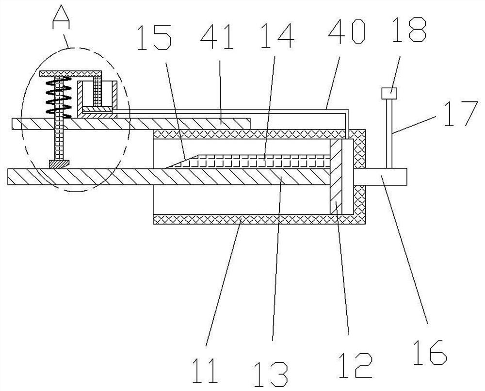
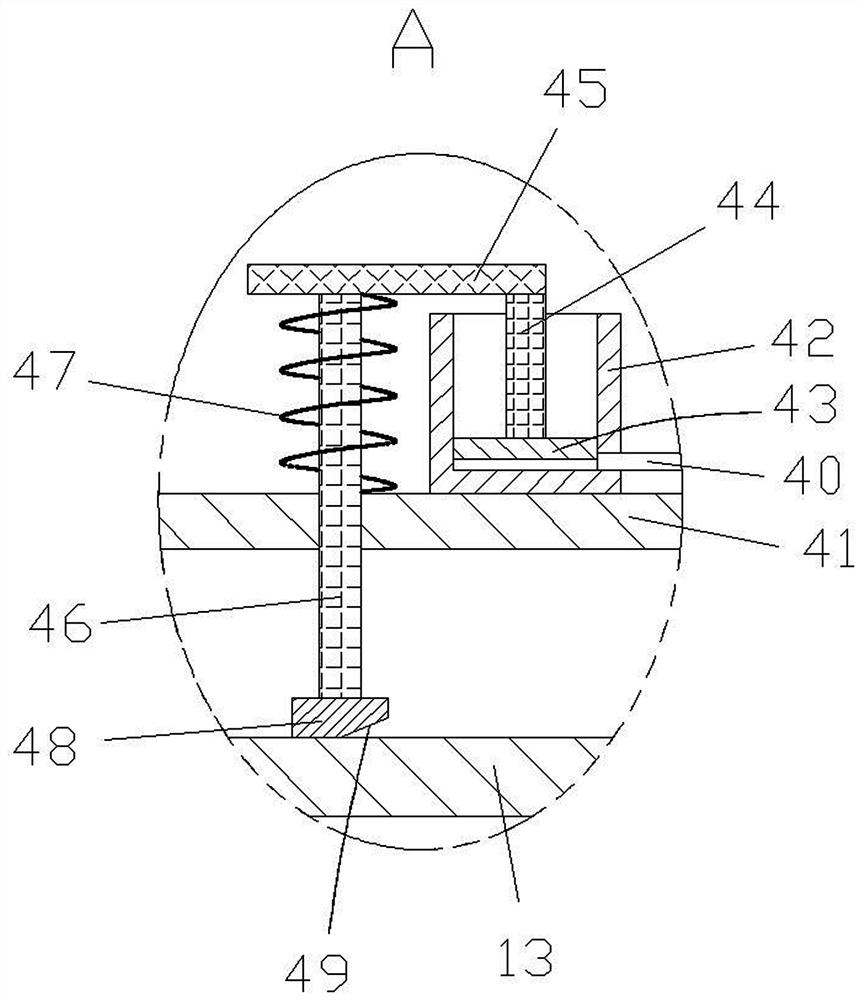
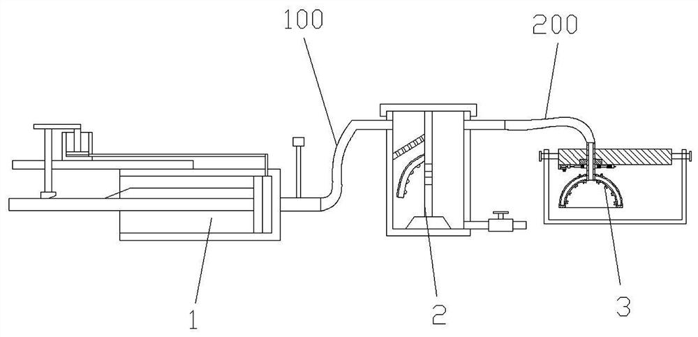
[0021] like Figure 1-2 As shown, the vacuum pumping device 1 provided by the present invention includes a first barrel 11, a first air pipe 16 is arranged at the bottom of the first barrel 11, and a vacuum breaking pipe 17 is arranged on one side of the first air pipe 16, and the vacuum breaking pipe 17 is installed on the top There is a vacuum breaker valve 18. The first barrel 11 is slidably connected to the first piston plate 12 , one side of the first piston plate 12 is fixedly connected to the first piston rod 13 , and a first push-pull for controlling the reciprocating movement of the first piston rod 13 is installed on the outside of the first barrel 11 The first push-pull device adopts the prior art, which will not be repeated here. One side of the first barrel 11 is fixedly connected to the fixing plate 41 , one side of the fixing plate 41 is fixedly connected to the second barrel 21 , the second barrel 21 is slidably connected to the second piston plate 43 , and is...


PUM


Abstract

The invention discloses a vacuumizing device for milking dairy cows. The vacuumizing device comprises a first barrel body, wherein a first air pipe is arranged at the barrel bottom of the first barrel body; a first piston plate is slidably connected into the first barrel body; one side of the first piston plate is fixedly connected with a first piston rod; a first push-pull device for controlling the first piston rod to reciprocate is arranged at the outer side of the first barrel body; one side of the first barrel body is fixedly connected with a fixing plate; one side of the fixing plate is fixedly connected with a second barrel body; a second piston plate is slidably connected into the second barrel body; one side of the second piston plate is fixedly connected with a second piston rod; and one end of the second piston rod is provided with a second push-pull device for controlling the second piston rod to do reciprocating motion. The vacuumizing device has the advantages that the vacuumizing device can slowly perform vacuumizing, so that the breasts of a dairy cow gradually adapt to the suction force; and after the dairy cow adapts to the suction force, the suction force can be increased suddenly, and milk of the dairy cow can be fully sucked out.

Description

technical field [0001] The invention relates to the technical field of milking equipment, in particular to a vacuuming device for milking cows. Background technique [0002] During the milking process, atmospheric pressure is formed by the action of vacuum, and suction is formed by the milking cup to extract and collect the milk. The vacuum pumping device for milking cows in the prior art usually adopts a vacuum pump. Milk is usually evacuated directly, the pumping speed is fast, and it directly acts on the nipple of the cow, which is easy to cause damage to the udder of the cow. SUMMARY OF THE INVENTION [0003] The purpose of the present invention is to propose a vacuuming device for milking cows in order to solve the shortcomings in the prior art. [0004] In order to achieve the above object, the present invention adopts the following technical solutions: [0005] A vacuum pumping device for milking cows, the vacuum pumping device comprises a first barrel body, a fir...

Claims


Application Information

Patent Timeline
Patent Type & Authority Applications(China)
IPC IPC(8): A01J5/04A01J5/06A01J7/00
CPCA01J5/06A01J5/047A01J7/00
Inventor 王磊刘纯利张平娟娄树勇孙文洋
Owner ANHUI SCI & TECH UNIV
Learn More