
Liquid reservoir

A technology for a liquid storage container and a container is applied in the liquid storage field, which can solve the problems of low manufacturing cost and high structural manufacturing cost, and achieve the effects of reducing the number of processing workers, simple structure and reliable support.

Active Publication Date: 2012-06-13
ZHEJIANG SANHUA AUTOMOTIVE COMPONENTS CO LTD
View PDF1 Cites 0 Cited by
  • Summary
  • Abstract
  • Description
  • Claims
  • Application Information

AI Technical Summary

Problems solved by technology

[0004] The technical problem to be solved and the technical task proposed by the present invention are to overcome the structural deficiencies of the prior art and the resulting high manufacturing cost, and to provide a suction pipe that can be fully supported and There is no adverse effect on the suction of the refrigerant, and the liquid receiver can fully realize the suction effect and reduce the manufacturing cost.

Method used


Image

  • Liquid reservoir
  • Liquid reservoir
  • Liquid reservoir

Examples


Embodiment Construction

[0021] The following reference figure 1 To figure 2 , A detailed description of the embodiment of the present invention.

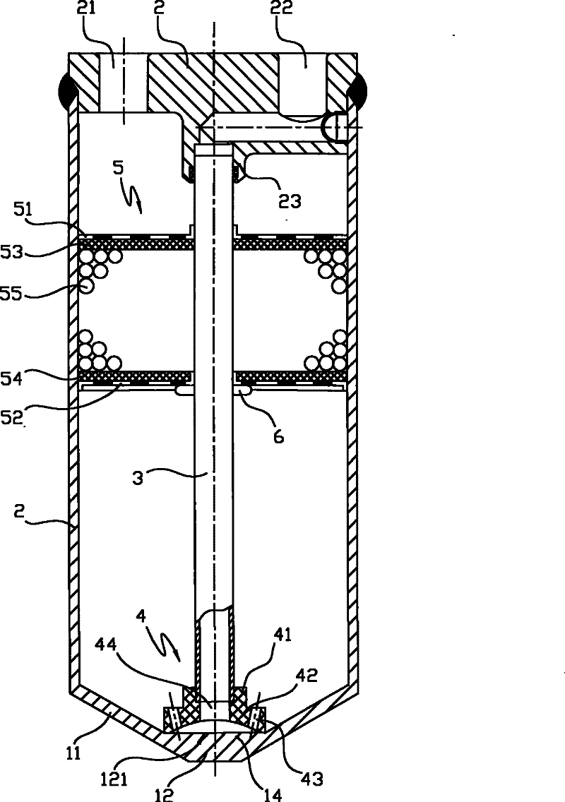
[0022] figure 1 Shown is an axial sectional view of the reservoir of the embodiment of the present invention. The structure of the reservoir is that a plug 2 is formed on the upper part of the container 1, and the lower portion of the plug 2 is joined to the container 1.

[0023] The plug 2 has an inlet 21 connected to a refrigerant inlet pipe (not shown) and an outlet 22 connected to a refrigerant outlet pipe (not shown). The upper end opening of the container 1 is as figure 1 Shown are fitted with said plug 2 and welded together.

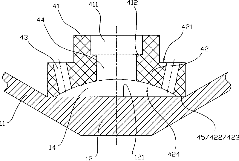
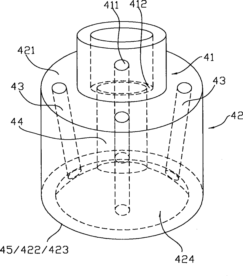
[0024] In addition, the lower part of the container 1 is formed with an inclined part 11 and a bottom part 12, and the bottom part has a flat surface 121. In addition, a supporting member 4 for supporting the pipette 3 is arranged on the inclined portion 11 and the connected bottom portion 12.

[0025] In addition, a drying section ...


PUM


Abstract

A liquid reservoir is applied to a cold and warm system of an automotive air conditioning and aims at solving the problem of high production cost owing to the deficiency of the technique in the structure. The invention comprises a container and a support piece which is arranged in the inner space of the container and is used for supporting a pipette. The invention is characterized in that the twodirections contrary to the supporting piece are provided with a cylinder part which is provided with the pipette and a supporting part which is arranged at the bottom of the container respectively; communicating pores which are distributed surrounding the cylinder part for passing cooling medium are formed in the supporting piece; the liquid cooling medium can be fully sucked with the pipette. The supporting piece forms a supporting part by arranging an upward recess at the bottom surface of a circular tray; therefore, the structure is simple and the processing procedures are reduced, therebyreducing the cost of the liquid reservoir.

Description

Technical field [0001] The invention is a liquid reservoir used in the cooling and heating system of the automobile air conditioner. Background technique [0002] Patent Document 1 (Japanese Unexamined Publication No. 06-27232) describes a liquid reservoir. Compared with the pipette shown in FIG. 5, the bottom of the liquid reservoir is provided with a support around the bottom 1a of the container 1. The supporting member 7, the designated interval d between the bottom of the supporting member 7 and the bottom 1a of the container 1 is used to prevent the pipette 4 from falling; in addition, the middle portion of the pipette 4 is provided with a disc-shaped bottom plate 2 and 3. Fill a desiccant between the bottom plates 2 and 3; in addition, the patent document 1 figure 1 A pier for positioning is provided on the suction pipe in, and the pier uses a disc-shaped bottom plate 11 to position the suction pipe. Further, as a type of reservoir for preventing the drop of the pipette th...

Claims


Application Information

Patent Timeline
Patent Type & Authority Patents(China)
IPC IPC(8): F25B43/00
Inventor 张自翔吕小丹
Owner ZHEJIANG SANHUA AUTOMOTIVE COMPONENTS CO LTD
Learn More