
Mineral water purification equipment

A technology for water purification equipment and mineral water, which is applied in water/sewage treatment, water/sludge/sewage treatment, sedimentation tank, etc., and can solve problems such as threats to safety, low market acceptance, and reduced equipment efficiency.

Inactive Publication Date: 2020-10-23
姜平乐
View PDF0 Cites 0 Cited by
  • Summary
  • Abstract
  • Description
  • Claims
  • Application Information

AI Technical Summary

Problems solved by technology

[0002] The mineral water purification process often involves the settlement of mineral water. Because mineral water will precipitate some impurities under low-temperature static conditions, the types of impurities are mostly metal-containing precipitates. Due to the existence of the above shortcomings, on the one hand, the market acceptance is not high. Because most people think these sediments are harmful substances, and considering the health of personnel, if these precipitates are removed, some other beneficial substances will be left in the water body, which can also achieve beneficial purposes for the human body and absorb more Minerals will cause the occurrence of stones in the human body, which will greatly threaten the safety of personnel. The existing separation equipment often uses natural precipitation, which cannot fully absorb and discharge the sediment according to the water layer and depth of the sediment. In addition to the equipment, this will reduce the working efficiency of the equipment, and the actual working efficiency of the equipment will be reduced due to the existence of the above shortcomings

Method used


Image

  • Mineral water purification equipment
  • Mineral water purification equipment
  • Mineral water purification equipment

Examples


Embodiment Construction

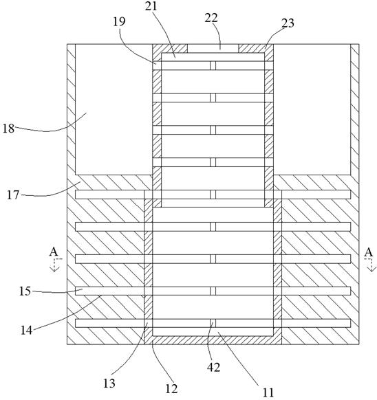
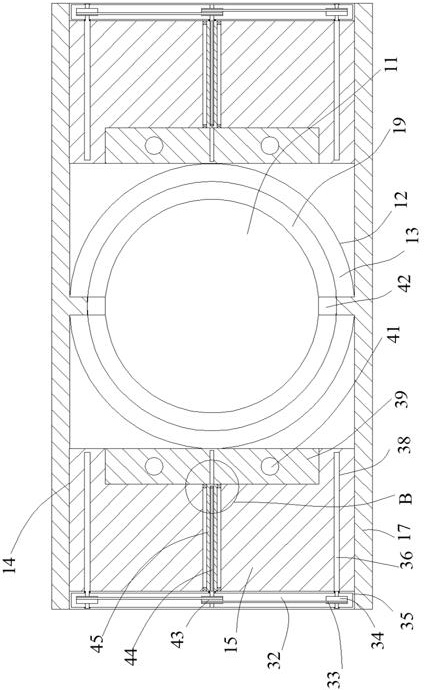
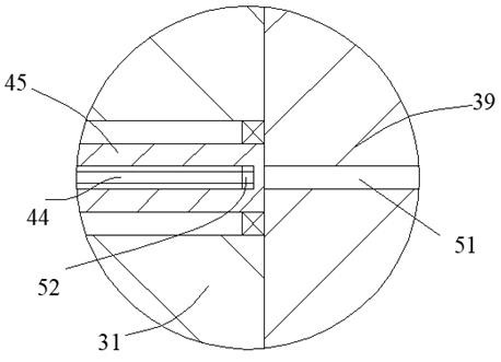
[0018] Such as Figure 1-Figure 3 As shown, the present invention is described in detail. For the convenience of description, the orientations mentioned below are now stipulated as follows: figure 1 The up, down, left, right, front and back directions of the projection relationship are consistent. A mineral water purification equipment of the present invention includes a box body 17, a top cavity 18 is arranged in the box body 17, and a top slide is provided for sliding in the top cavity 18. Box 23, the bottom side of the top sliding box 23 is provided with a bottom box 12 fixedly connected with the box 17, the bottom box 12 is provided with an inner cavity 11, and the end wall of the inner cavity 11 is connected There are several passing cavities 13, the top slide box 23 is provided with a cavity 21, one side of the cavity 21 is connected with a top hole 22, and the end wall of the cavity 21 is connected with a plurality of passing cavities 19, The top sliding box 23 is arra...


PUM


Abstract

The invention discloses mineral water purification equipment. The equipment includes a box body, a top cavity is formed in the box body, a top sliding box is arranged in the top cavity in a sliding manner, a bottom box body fixedly connected with the box body in a matched manner is arranged on the lower side of the top sliding box, an inner cavity is formed in the bottom box body, a plurality of penetrating cavities are formed in the end wall of the inner cavity in a communicating manner, an accommodating cavity is formed in the top sliding box, a top hole is formed in one side of the accommodating cavity in a communicating manner, and a plurality of passing cavities are formed in the end wall of the accommodating cavity in a communicating manner. According to the equipment, the bottom boxbody and the top sliding box on the lower side and the upper side slide relative to each other, and then the passing cavities and the penetrating cavities are opposite to each other, so that mineralwater can be fully guided out to the external space of the equipment by utilizing a layered guide-out structure in the equipment after sedimentation.

Description

technical field [0001] The invention relates to the technical field of mineral water purification equipment, in particular to a mineral water purification equipment. Background technique [0002] The mineral water purification process often involves the settlement of mineral water. Because mineral water will precipitate some impurities under low-temperature static conditions, the types of impurities are mostly metal-containing precipitates. Due to the existence of the above shortcomings, on the one hand, the market acceptance is not high. Because most people think these sediments are harmful substances, and considering the health of personnel, if these precipitates are removed, some other beneficial substances will be left in the water body, which can also achieve beneficial purposes for the human body and absorb more Minerals will cause the occurrence of stones in the human body, which will greatly threaten the safety of personnel. The existing separation equipment often us...

Claims


Application Information

Patent Timeline
IPC IPC(8): C02F1/00B01D21/02B01D21/24
CPCB01D21/02B01D21/245C02F1/00C02F2001/007
Inventor 姜平乐
Owner 姜平乐
Learn More