
Conveying device for oil well oil extraction

A conveying device and oil conveying technology, which is applied in the fields of fluid production, earth-moving drilling, wellbore/well components, etc., can solve the problems of low efficiency and labor consumption, achieve flexible device adjustment, avoid device falling, and enhance the scope of use. Effect

Pending Publication Date: 2020-12-25
黄山联合应用技术研究院
View PDF0 Cites 0 Cited by
  • Summary
  • Abstract
  • Description
  • Claims
  • Application Information

AI Technical Summary

Problems solved by technology

[0004] The purpose of the present invention is to solve the problem of labor-intensive and low efficiency in the prior art, and propose a delivery device for oil well production

Method used


Image

  • Conveying device for oil well oil extraction
  • Conveying device for oil well oil extraction
  • Conveying device for oil well oil extraction

Examples


Embodiment 1

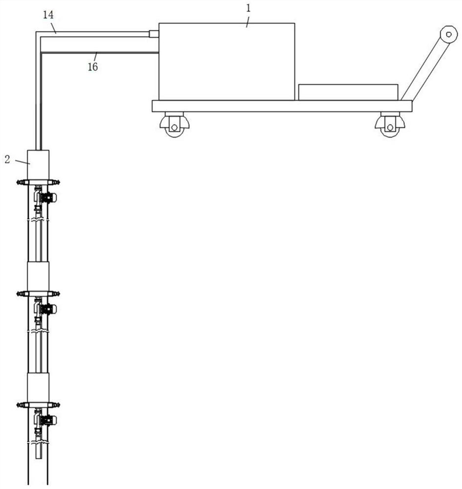
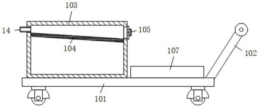
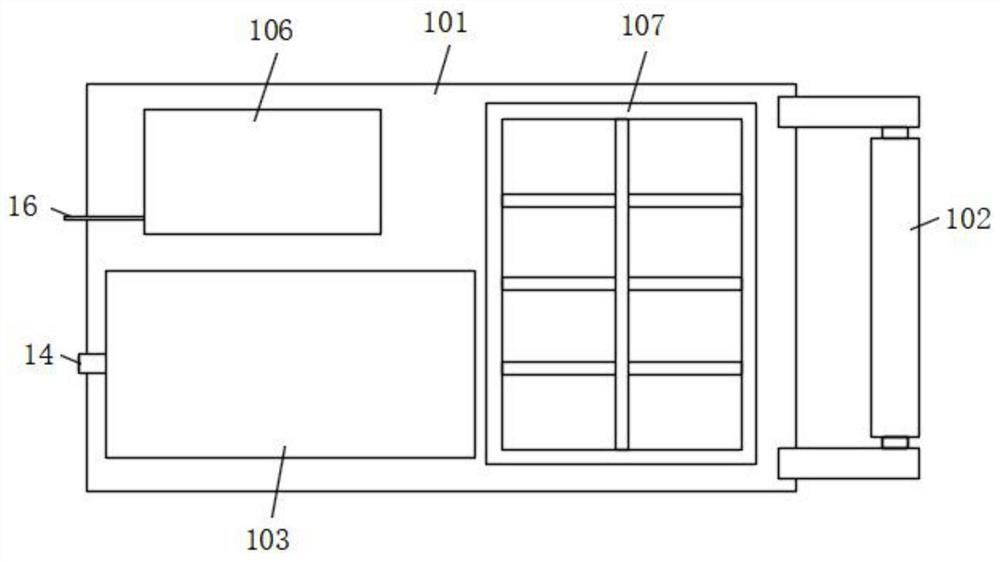
[0032] refer to Figure 1-5 , a delivery device for oil well production, comprising a push mechanism 1 and an oil delivery mechanism 2, a plurality of oil delivery mechanisms 2 are provided, the push mechanism 1 includes a push trolley 101, a push handle 102 is installed on one side of the push trolley 101, and the push trolley 101 An oil storage tank 103 is fixed at the front end of one side of the top surface, a filter screen 104 is fixed on the inner wall of the upper end of the oil storage tank 103, and a miscellaneous hole is opened on the upper side of the oil storage tank 103, and a sealing door body is installed on the outer wall of the miscellaneous hole through the hinge rotation 105, a generator 106 is also installed at the rear end of one side of the top surface of the push trolley 101, and a placement plate 107 is also fixed on the other side of the top surface of the push trolley 101. There are threaded holes, and the inner walls of the threaded holes are all fix...

Embodiment 2

[0035] Such as figure 1 and 4 As shown, this embodiment is basically the same as Embodiment 1. Preferably, two adjacent circular plates 3 in the two oil delivery mechanisms 2 are welded with fixed rings 17 at the ends close to each other, and the fixed rings 17 are each provided with two They are symmetrically distributed on both sides of the circular plate 3, and fixed ropes 18 are connected between two adjacent fixing rings 17 on the same side.

[0036] In this embodiment, two adjacent oil delivery mechanisms 2 are fixedly connected by the fixed rope 18, so that the fixing effect between the oil delivery mechanisms 2 is better, and the oil delivery mechanism 2 falls off and the device is prevented from falling.

Embodiment 3

[0038] Such as figure 2 and 3 As shown, this embodiment is basically the same as Embodiment 1. Preferably, the filter screen 104 is inclined downward from the outside of the pushing trolley 101 to the inside, and the sealing door 105 is located on the lower side of the filter screen 104 .

[0039] The placing tray 107 is arranged in a grid shape, and the outer wall of the push handle 102 is also fixed with a non-slip pad.

[0040] In this embodiment, the filter screen 104 is arranged at a slant, so that oil can be easily filtered through flow, and the efficiency of oil filtration is greatly improved.


PUM


Abstract

The invention discloses a conveying device for oil well oil extraction. The conveying device comprises a pushing mechanism and a plurality of petroleum conveying mechanisms, the pushing mechanism comprises a pushing trolley, a pushing handle is installed on one side of the pushing trolley, an oil storage tank is fixed to the front end of one side of the top face of the pushing trolley, a filter screen is fixed to the inner wall of the upper end of the oil storage tank, an impurity removing hole is further formed in one side of the upper end of the oil storage tank in a penetrating mode, a sealing door body is rotatably installed at one end of the outer wall of the impurity removing hole through hinges, a generator is further installed at the rear end of one side of the top face of the pushing trolley, and a containing disc is further fixed to the other side of the top face of the pushing trolley. The petroleum conveying mechanisms comprise circular plates, threaded holes are formed inthe side walls of the circular plates, and threaded columns are fixedly connected to the inner walls of the threaded holes through threads. The conveying device is reasonable in design, stable in operation, capable of achieving full exploitation operation of petroleum in an oil well, flexible in adjustment and capable of conveniently achieving oil absorption operation on hoistways of different specifications, and the application range of the device is greatly widened.

Description

technical field [0001] The invention relates to the technical field of oil well production equipment, in particular to a delivery device for oil well production. Background technique [0002] In order to extract oil, the holes drilled according to the well layout system of the oil field development plan, the passage of oil rising from the bottom of the well to the well head, the oil well is the hole drilled by the drilling method, and the oil will be ejected under the pressure at this time. [0003] The existing oil delivery device has its own oil pressure to realize the injection of oil. After a certain amount of oil is injected, the oil reserves deep in the surface are insufficient and the pressure decreases. At this time, a pump will be added at the well mouth to suck the oil out. However, in actual use, since the depth of the well can reach thousands of meters, adding a pump at the mouth of the well will make it difficult to extract all the oil from the depth of the well...

Claims


Application Information

Patent Timeline
Patent Type & Authority Applications(China)
IPC IPC(8): E21B43/00E21B43/34F16F15/067
CPCE21B43/121E21B43/34F16F15/067
Inventor 郑平齐小峰弓波
Owner 黄山联合应用技术研究院
Learn More