
A large displacement pump combined with a vane pump and a gear pump

A vane pump with large displacement technology, applied in pumps, rotary piston pumps, rotary piston machines, etc., can solve problems such as poor sealing of working volume, unbalanced radial force, and increased noise of gear pumps, and achieve Low noise, easy processing, high pressure effect

Inactive Publication Date: 2015-11-11
BEIJING UNIV OF TECH
View PDF8 Cites 0 Cited by
  • Summary
  • Abstract
  • Description
  • Claims
  • Application Information

AI Technical Summary

Problems solved by technology

[0003] The purpose of the present invention is to provide a large-displacement pump combined with a vane pump and a gear pump through the analysis and integration of the vane pump rotor structure and the gear structure of the gear pump, so as to solve the problem of a traditional vane pump with a complex structure and a small displacement. The problem is that when the pump is running, because the position of the blade and the shaft is fixed, it can avoid the phenomenon of scratching, the surface wear of the blade and the stator, and at the same time, it can avoid the working volume of the gear pump from being tightly sealed, the radial force is unbalanced, the oil is trapped, and the noise becomes louder. Low pressure, difficult oil absorption and other problems make the working state more stable and the output flow is significantly improved

Method used


Image

  • A large displacement pump combined with a vane pump and a gear pump
  • A large displacement pump combined with a vane pump and a gear pump

Examples


Embodiment Construction

[0011] The present invention will be further described below in conjunction with the drawings and embodiments.

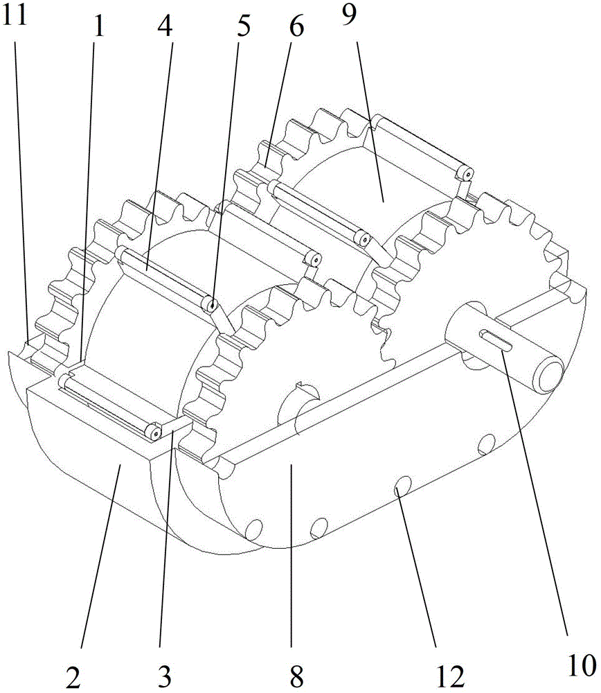
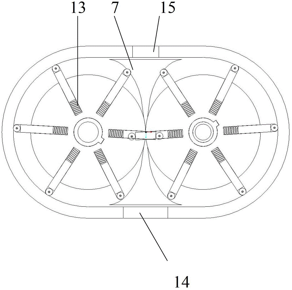
[0012] In a structure of a large displacement pump combining a vane pump and a gear pump, a pump body rear cover 1; a pump body 2; a pump body front cover 3; a blade 4; a roller 5; a gear 6; a guide plate 7; Cover 8; rotor 9; rotating shaft 10; gear rear cover 11; bolt 12; spring 13; oil inlet 14; oil outlet 15. The top and bottom of the pump body 2 are respectively provided with an oil outlet 15 and an oil inlet 14, The pump body 2 is provided with two rotors 9 circumscribed on the outer surface. The rotors 9 are sleeved on the rotating shaft 10. Each rotor 9 has six slides. The slides are equipped with blades 4 and are installed at the roots of the blades 4. There is a spring 13, and the top ends of the blade 4 are equipped with a roller 5 respectively. When the roller 5 is in contact with the guide plate 7 and guided by the guide plate 7, the blade 4 is returned to ...


PUM


Abstract

The invention relates to a high-duty pump combining a vane pump with a gear pump, and belongs to the technical field of hydraulic pump equipment manufacture. Vanes, end covers, rotors and a pump body form a sealed hydraulic chamber. A rotating shaft transmits a shaft torque input by a motor to the rotors and gears on the rotating shaft, the gears transmit the shaft torque to driven gears to drive another rotating shaft to rotate reversedly, and the rotors drive the movable vanes on the rotors to move back and forth in slides on the rotors under the guidance of guide plates when the rotors rotate. The vanes, the end covers, the rotors and the pump body form the sealed hydraulic chamber, and oil is driven to an oil outlet and extruded outside under the drive of the rotors. Compared with the existing vane pump, the pump has the characteristics of simple structure, easiness in processing, lower cost, no scraping or sticking, no abrasion on the surfaces of the vanes and the stators, and the like, and operates more stably; and the output flow rate of the pump is increased obviously. Compared with the existing gear pump, the pump has the advantages of easy oil absorption, high pressure, low noise, good stability, low power consumption, high working efficiency, and is suitable for large-tonnage hydraulic equipment.

Description

Technical field: [0001] The invention relates to a vane pump, in particular to a large displacement pump combined with a vane pump and a gear pump, and belongs to the technical field of hydraulic pump equipment manufacturing. Background technique: [0002] With the rapid development of economy and technology, hydraulic transmission technology has become more and more widely used in the fields of machinery manufacturing, metallurgy, chemical industry, building materials, construction, etc., and hydraulic equipment has higher and higher performance requirements for hydraulic power components. Gear pumps and vane pumps are commonly used in the past, but gear pumps have the disadvantages of high noise, poor stability, high power consumption, complex systems, and low work efficiency. Compared with gear pumps, vane pumps have the advantages of small flow, high cost, easy to wear on the surfaces of the blades and stators, and the phenomenon of scratching due to the unfixed positions of ...

Claims


Application Information

Patent Timeline
Patent Type & Authority Patents(China)
IPC IPC(8): F04C2/34
Inventor 胡洪平臧维
Owner BEIJING UNIV OF TECH
Learn More