
a vane pump

A vane pump and vane technology, which is applied in the field of hydraulic pumps, can solve problems such as cavitation caused by air suction, insufficient oil absorption, and influence on stable work, and achieve the effects of solving insufficient self-priming ability, avoiding cavitation, and prolonging service life.

Active Publication Date: 2021-06-29
江苏军源装备制造有限公司
View PDF0 Cites 0 Cited by
  • Summary
  • Abstract
  • Description
  • Claims
  • Application Information

AI Technical Summary

Problems solved by technology

[0002] The vane pump is a hydraulic power component widely used in hydraulic systems, but its self-priming ability is relatively poor. If the inlet supply oil pressure is low during operation, it will easily cause insufficient oil suction, resulting in cavitation, vibration and noise, and internal friction in the pump. The rapid wear of the pair accelerates the failure of the pump and affects the working life of the pump. Therefore, the problem of insufficient oil suction at the inlet of the vane pump has a great impact on its stable operation.

Method used


Image

  • a vane pump
  • a vane pump
  • a vane pump

Examples


Embodiment Construction

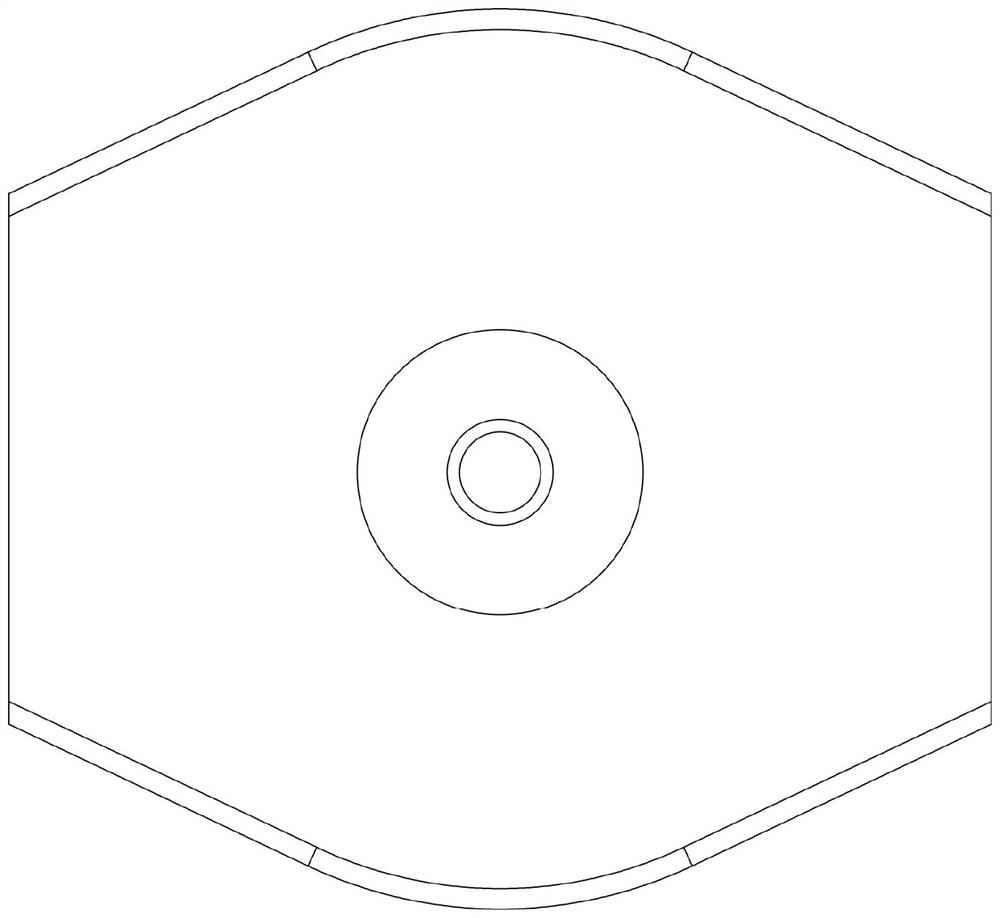
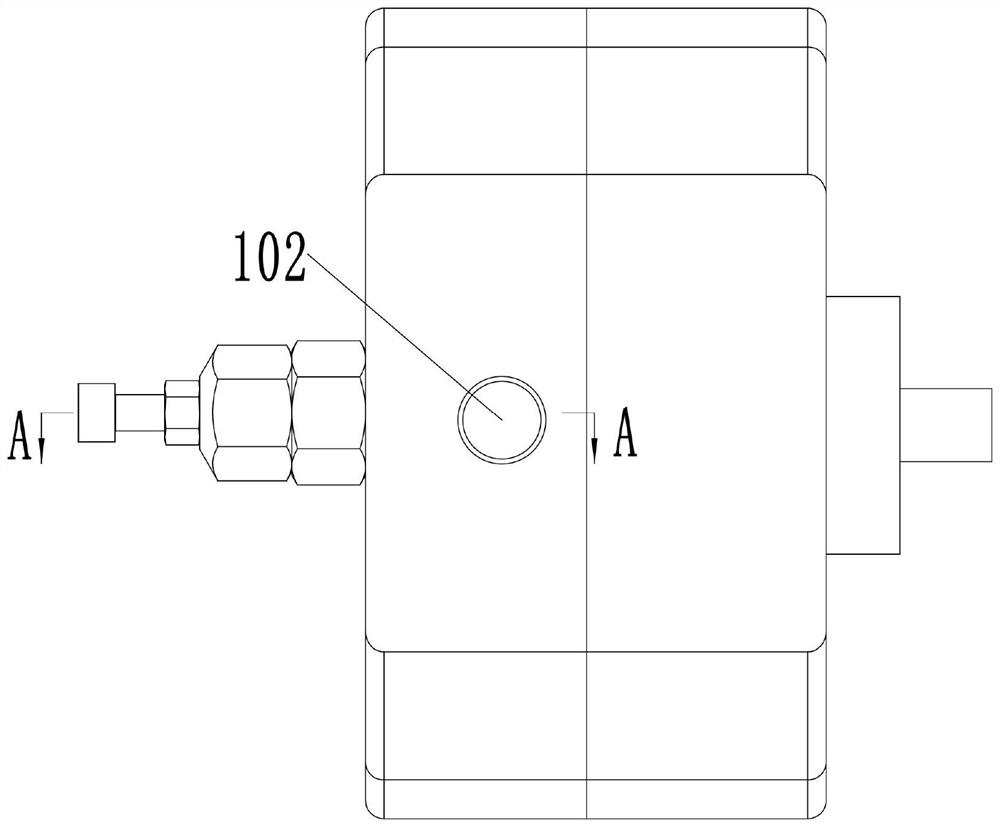
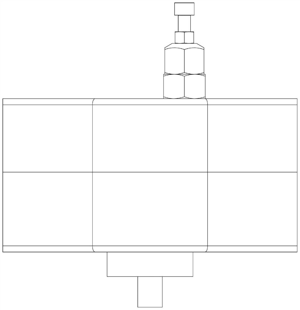
[0027] see Figure 1-12 As shown, a vane pump includes a pump casing 7, and an end cover 1 arranged at the opening of the pump casing 7; a rotating shaft 8 is rotatably connected between the end cover 1 and the pump casing 7, and the rotating shaft 8 is located at the end cover 1 and the eccentric position of the pump casing 7, one end of the rotating shaft 8 protrudes from the pump casing 7; a stator 3 is fixedly installed in the pump casing 7, and the stator 3 is coaxially arranged with the pump casing 7; A blade chamber 301 is provided; a rotor 4 is rotatably connected to the blade chamber 301, and the rotor 4 is coaxially arranged with the stator 3; A blade 5 is slidably connected in the connection groove 401; a gear chamber 403 is provided at the center of the rotor 4; a protruding tooth 402 is provided on the inner peripheral side wall of the gear chamber 403, and the rotating shaft 8 is fixedly installed with a protruding The internal gear 6 meshed with the teeth 402, ...


PUM


Abstract

The invention discloses a vane pump, which includes a pump casing and an end cover arranged at the opening of the pump casing; a rotating shaft is rotatably connected between the end cover and the pump casing, and the rotating shaft is located at an eccentric position between the end cover and the pump casing A stator is fixedly installed in the pump casing, and the stator is arranged coaxially with the pump casing; a vane cavity is provided in the stator; a rotor is connected to the vane cavity in rotation, and the rotor is coaxially arranged with the stator; The circumferential side of the rotor is slidingly connected with blades along its radial direction; a gear cavity is provided at the center of the rotor; protruding teeth are provided on the inner peripheral side wall of the gear cavity, and the rotating shaft is fixedly installed with protruding teeth. The internal gear with meshing teeth, the internal gear is located at the eccentric position of the rotor; the end cover and the end of the stator in the pump casing are provided with a flow distribution plate; the vane pump is not only simple in structure, but also can lift the oil suction chamber of the vane pump The internal pressure makes the oil absorption smoother.

Description

technical field [0001] The invention belongs to the technical field of hydraulic pumps, in particular to a vane pump. Background technique [0002] The vane pump is a hydraulic power component widely used in hydraulic systems, but its self-priming ability is relatively poor. If the inlet supply oil pressure is low during operation, it will easily cause insufficient oil suction, resulting in cavitation, vibration and noise, and internal friction in the pump. The rapid wear of the pair accelerates the failure of the pump and affects the working life of the pump. Therefore, the problem of insufficient oil suction at the inlet of the vane pump has a great impact on its stable operation. Contents of the invention [0003] (1) Technical problems to be solved [0004] The purpose of the present invention is to provide a vane pump which can increase the pressure in the oil suction cavity of the vane pump and make the oil suction smoother. [0005] (2) Technical solution [0006...

Claims


Application Information

Patent Timeline
Patent Type & Authority Patents(China)
IPC IPC(8): F04C2/10F04C2/344F04C11/00F04C15/00F04C15/06
CPCF04C2/084F04C2/10F04C2/344F04C11/005F04C15/00F04C15/06F04C15/062
Inventor 不公告发明人
Owner 江苏军源装备制造有限公司
Learn More