
Self-adaptive closed hydraulic oil tank

A hydraulic oil tank, self-adaptive technology, applied in the direction of oil supply tank device, fluid pressure actuation device, fluid pressure actuation system components, etc., can solve the problem of affecting the normal operation of the hydraulic system, increasing leakage, hydraulic pump cavitation, etc. problem, to achieve the effect of solving insufficient self-priming capacity, flexible layout, and high integration

Active Publication Date: 2020-04-24
LANZHOU UNIVERSITY OF TECHNOLOGY
View PDF7 Cites 3 Cited by
  • Summary
  • Abstract
  • Description
  • Claims
  • Application Information

AI Technical Summary

Problems solved by technology

These pollutants not only accelerate the wear of components, block the gaps and damping channels in the components, but also accelerate the oxidation and deterioration of the hydraulic medium, corrode the metal surface, and the excessive heat energy reduces the viscosity of the hydraulic medium, increases the leakage, and mixes the pollution in the hydraulic working medium. Seriously affect the reliability of the hydraulic system and the service life of the components
[0003] Most of the existing hydraulic oil tanks adopt an open structure, and the liquid level in the oil tank is connected to the atmosphere through an air filter. This kind of oil tank is very unfavorable for hydraulic pumps with poor self-priming ability, especially for hydraulic pumps working at high altitudes, and often The cavitation phenomenon of the hydraulic pump is caused by the decrease of the inlet pressure of the hydraulic pump, which seriously affects the normal operation of the hydraulic system.
In addition, most of the existing hydraulic oil tanks consider the heat dissipation of the oil tank itself. In order to extend the flow channel, reduce the flow rate, fully separate the air in the hydraulic medium and precipitate solid particles, the volume of the oil tank is generally designed according to 5 to 7 times the system flow rate, so that For occasions with limited space volume, especially for walking machinery, it is unsatisfactory
The existing hydraulic oil tank needs to operate the main pump device online to realize the filtration and purification of the hydraulic medium, which cannot realize the energy-saving offline cycle cleaning, let alone the degassing and dehydration function of the hydraulic medium in the online and offline state

Method used


Image

  • Self-adaptive closed hydraulic oil tank
  • Self-adaptive closed hydraulic oil tank
  • Self-adaptive closed hydraulic oil tank

Examples


Embodiment Construction

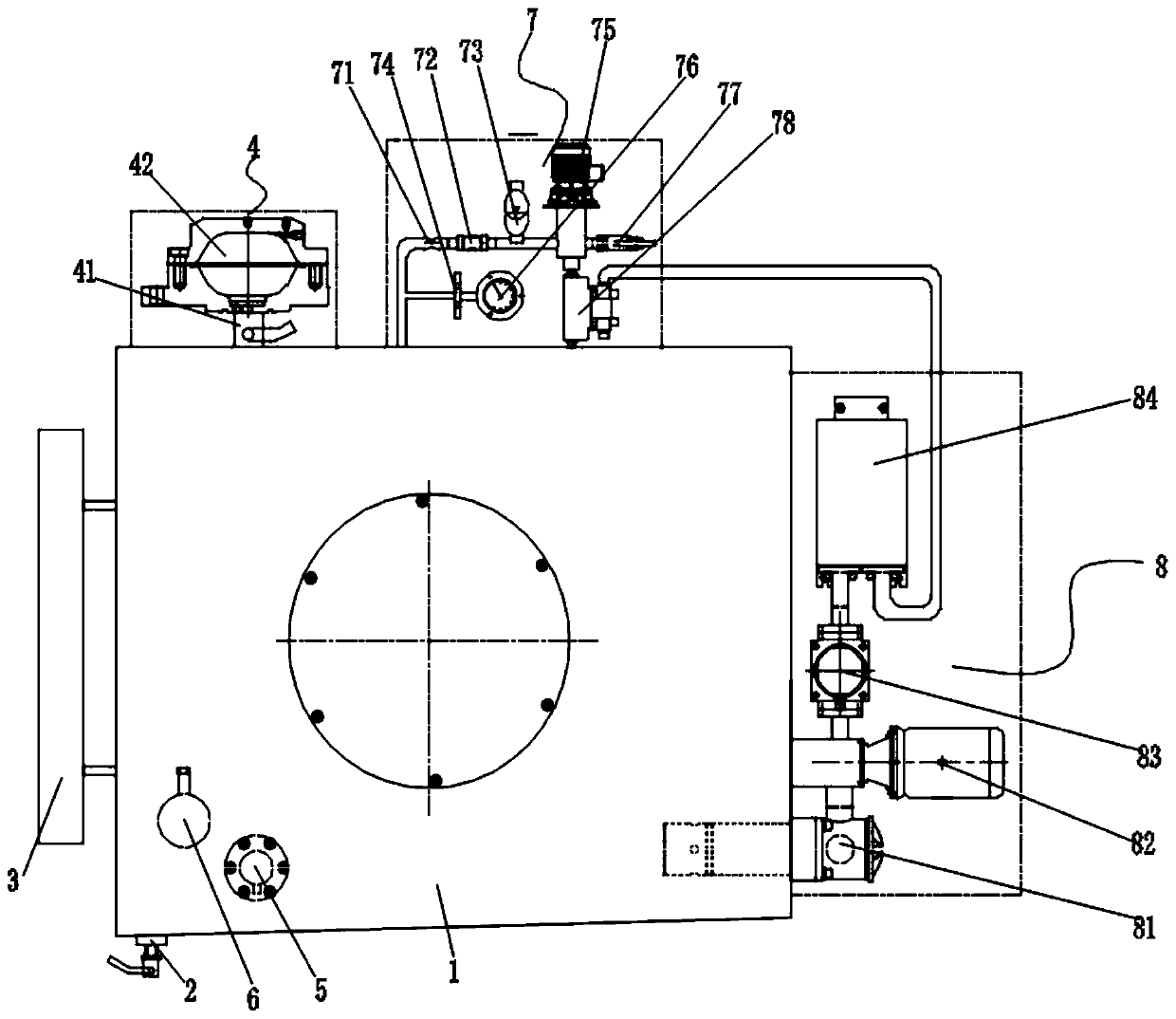
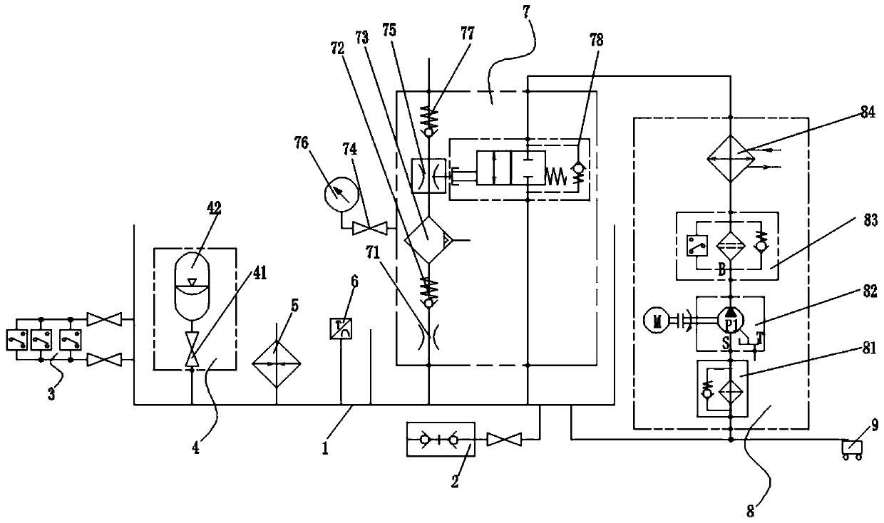
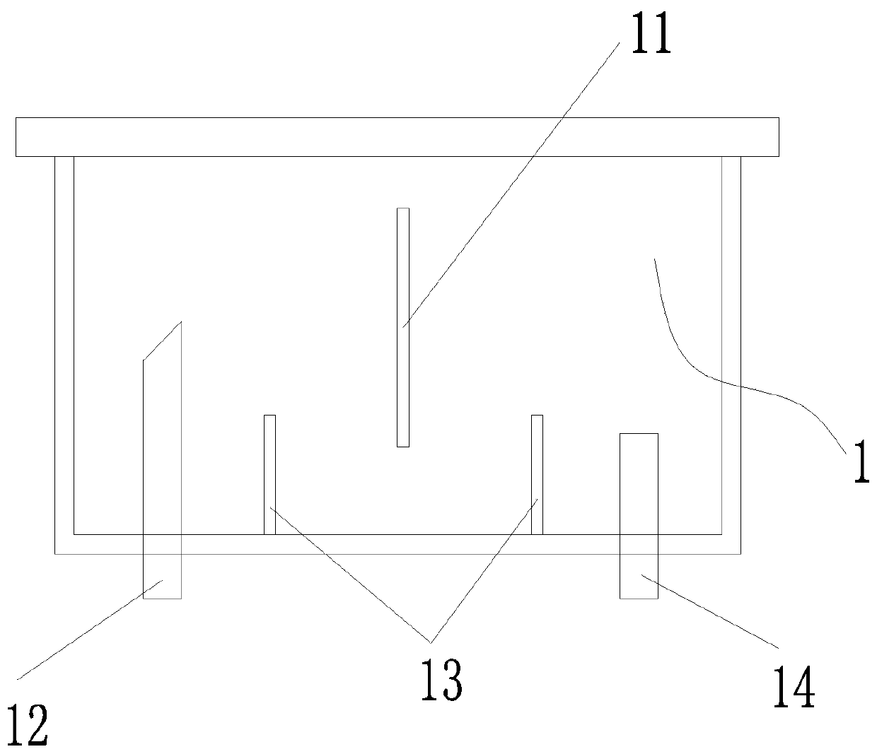
[0022] figure 1 It is a structural schematic diagram of the present invention; figure 2 It is a structural schematic diagram of the hydraulic system of the present invention; image 3 It is a schematic diagram of the internal arrangement structure of the box body of the present invention; Figure 4 It is a schematic diagram when the vacuum generator of the present invention runs downward; Figure 5 It is a schematic diagram of the upward operation of the vacuum generator of the present invention; as shown in the figure; an adaptive closed hydraulic oil tank includes a fuel tank body 1, a liquid-gas isolation mechanism 4 arranged on the fuel tank body 1, and a liquid-gas isolation mechanism 4 arranged on the top of the fuel tank body 1 The degassing and dehydrating mechanism 7 and the filtration and cooling cycle mechanism 8 arranged on the fuel tank body 1; the degassing and dehydrating mechanism includes a damping channel 71 communicated with the inside of the fuel tank bo...


PUM


Abstract

The invention discloses a self-adaptive closed hydraulic oil tank. The self-adaptive closed hydraulic oil tank comprises an oil tank body, a liquid-gas isolation mechanism arranged on the oil tank body, a degassing and dewatering mechanism arranged at the top of the oil tank body and a filtering, cooling and circulating mechanism arranged on the oil tank body; the degassing and dewatering mechanism comprises a damping channel communicated with the interior of the oil tank body, an air incoming one-way valve connected with the damping channel, an oil-water separator connected with the air incoming one-way valve, a vacuum generator connected with the oil-water separator and a high-speed stroke reversing valve; the high-speed stroke reversing valve is communicated with the filtering, and cooling circulating mechanism; and the vacuum generator is connected with an air exhaust one-way valve for exhausting gas. With the self-adaptive closed hydraulic oil tank provided by the technical schemes of the invention adopted, cyclic degassing and dewatering can be conducted; cyclic filtering, cooling and continuous heating can be also conducted; pollutants in hydraulic oil are well controlled; the working temperature range of a hydraulic medium is maintained; and the problem of the insufficient self-priming capacity of a hydraulic pump is solved; and high adaptability is realized.

Description

technical field [0001] The invention relates to the field of oil tanks, in particular to an adaptive closed hydraulic oil tank. Background technique [0002] The experience of the actual operation of the hydraulic system shows that pollution is the main reason for the failure of the hydraulic system. Pollutants in hydraulic systems come from residues in the manufacturing process of hydraulic components, external immersion, and products during system operation, mainly including solid particles, water, air, chemical pollutants, microorganisms, and pollution energy. These pollutants not only accelerate the wear of components, block the gaps and damping channels in the components, but also accelerate the oxidation and deterioration of the hydraulic medium, corrode the metal surface, and the excessive heat energy reduces the viscosity of the hydraulic medium, increases the leakage, and mixes the pollution in the hydraulic working medium. These substances seriously affect the rel...

Claims


Application Information

Patent Timeline
Patent Type & Authority Applications(China)
IPC IPC(8): F15B1/26F15B21/041F15B21/0423F15B21/0427F15B21/044
CPCF15B1/26F15B21/0423F15B21/041F15B21/0427F15B21/044
Inventor 柴红强杨国来伍国果李广东白桂香
Owner LANZHOU UNIVERSITY OF TECHNOLOGY
Learn More