Automobile rotating shaft rust prevention auxiliary device capable of recycling lubricating oil

An auxiliary device and lubricating oil technology, applied in lubrication systems, vehicle parts, transportation and packaging, etc., can solve the problems of waste of resources, fatigue wear, poor anti-fatigue performance, etc., and achieve the effect of saving resources

Inactive Publication Date: 2021-09-07
杭州润云会计事务所有限公司
View PDF0 Cites 0 Cited by
  • Summary
  • Abstract
  • Description
  • Claims
  • Application Information

AI Technical Summary

Problems solved by technology

[0002] The shaft that must be used for the main parts of the link product and is used to bear both bending moment and torque in the rotating work is called the rotating shaft. The wear of the rotating shaft is a common equipment problem during the use of the shaft, which is mainly caused by the metal characteristics of the shaft. : Although the metal has high hardness, it has poor yield, poor impact resistance, and poor fatigue resistance, so it is easy to cause adhesive wear, abrasive wear, fatigue wear, fretting wear, etc., so it is necessary to maintain and protect the rotating shaft
[0003] However, the existing equipment cannot automatically position and clamp rotating shafts of different sizes, which affects the installation time of the equipment, which may affect the working efficiency of the equipment, and cannot recover and reuse excess lubricating oil. , which may cause a waste of resources and increase the cost; therefore, those skilled in the art provide an auxiliary device for rust prevention of automobile shafts that can recycle lubricating oil to solve the problems raised in the above-mentioned background technology

Method used


Image

  • Automobile rotating shaft rust prevention auxiliary device capable of recycling lubricating oil
  • Automobile rotating shaft rust prevention auxiliary device capable of recycling lubricating oil
  • Automobile rotating shaft rust prevention auxiliary device capable of recycling lubricating oil

Examples


Embodiment Construction

[0020] The following will clearly and completely describe the technical solutions in the embodiments of the present invention with reference to the accompanying drawings in the embodiments of the present invention. Obviously, the described embodiments are only some, not all, embodiments of the present invention. Based on the embodiments of the present invention, all other embodiments obtained by persons of ordinary skill in the art without making creative efforts belong to the protection scope of the present invention.

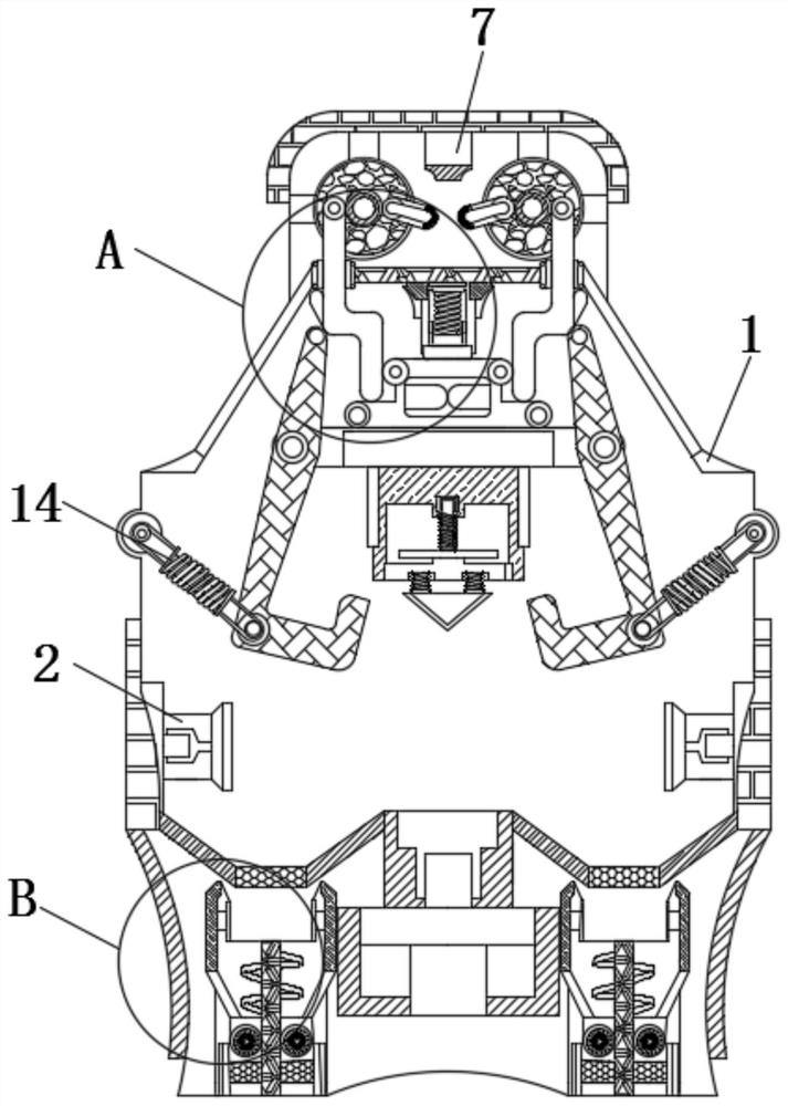
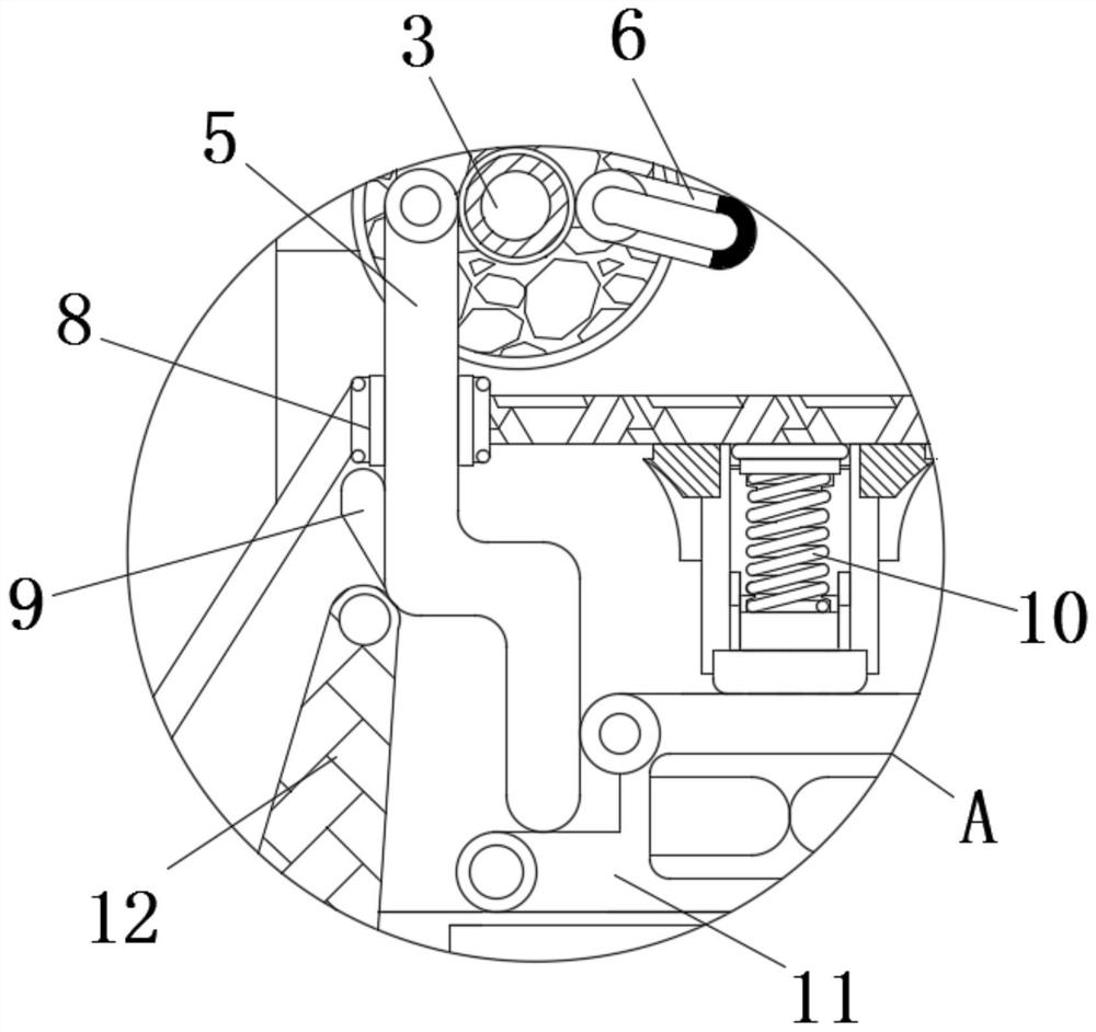
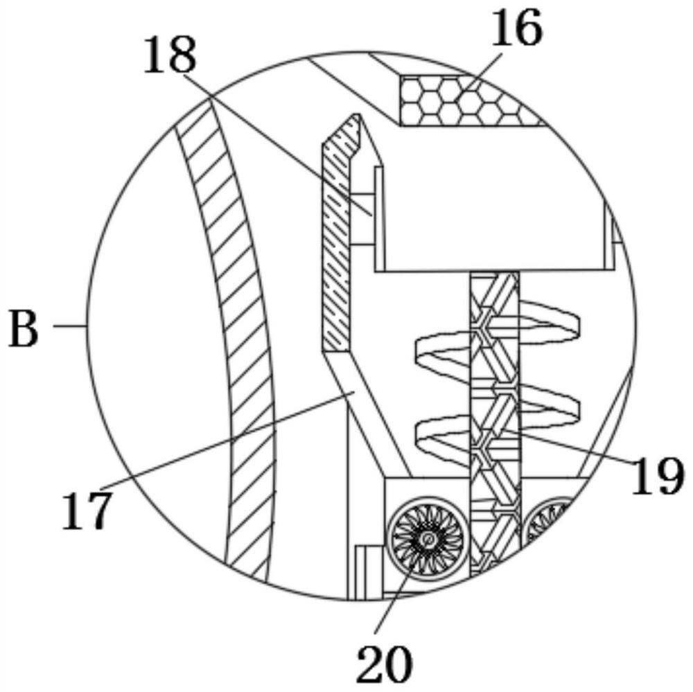
[0021] see Figure 1-5 , a kind of recyclable lubricating oil reusable automobile shaft anti-rust auxiliary device, comprising a fuel spray frame 1, the left and right sides of the inner wall of the fuel spray frame 1 are fixedly connected with nozzles 2, and the internal rotation of the fuel spray frame 1 is connected with a drive shaft 3. The outside of the driving shaft 3 is sleeved with a jacket turntable 4. The shape of the jacket turntable 4 is circular....


PUM


Abstract

The invention relates to the technical field of automobile rotating shaft rust prevention equipment, in particular to an automobile rotating shaft rust prevention auxiliary device capable of recycling lubricating oil. The device comprises an oil spraying frame, nozzles are fixedly connected to the left side and the right side of the inner wall of the oil spraying frame, a driving rotating shaft is rotatably connected to the interior of the oil spraying frame, the outer portion of the driving rotating shaft is sleeved with an outer sleeve rotating disc, the front surface of the outer sleeve rotating disc is movably connected with a downward pressing push rod through a shaft, the front surface of the outer sleeve rotating disc is fixedly connected with a limiting clamping pin, and a self-locking block is fixedly connected to the position, located above the limiting clamping pin, in the oil spraying frame. Redundant lubricating oil flows into a filter element plate below, is filtered by the filter element plate and flows out of an oil storage tank below an oil pipe, and a rotating shaft is driven to drive an oil well pump to rotate through a belt, so that the recovered lubricating oil is recycled by the oil well pump, and resources can be well saved; and therefore, the effect of recycling the lubricating oil is achieved.

Description

technical field [0001] The invention relates to the technical field of anti-rust equipment for automobile shafts, in particular to an anti-rust auxiliary device for automobile shafts that can recycle lubricating oil. Background technique [0002] The shaft that must be used for the main parts of the link product and is used to bear both bending moment and torque in the rotating work is called the rotating shaft. The wear of the rotating shaft is a common equipment problem during the use of the shaft, which is mainly caused by the metal characteristics of the shaft. : Although the metal has high hardness, it has poor yield, poor impact resistance, and poor fatigue resistance, so it is easy to cause adhesive wear, abrasive wear, fatigue wear, fretting wear, etc. Therefore, maintenance and protection of the rotating shaft is required. [0003] However, the existing equipment cannot automatically position and clamp rotating shafts of different sizes, which affects the installati...

Claims


Application Information

Patent Timeline
Patent Type & Authority Applications(China)
IPC IPC(8): B60R17/00
CPCB60R17/00
Inventor 杨柳青
Owner 杭州润云会计事务所有限公司
Why Eureka
Try Eureka