A circular workpiece clamping device for electric discharge machine tools

A technology of electric discharge machine tools and workpiece clamps, which is applied in the direction of electric processing equipment, metal processing equipment, manufacturing tools, etc., can solve the problems of poor adjustment, small use range, poor work stability, etc., and achieve improved stability, wide use range, The effect of high work stability

Active Publication Date: 2019-11-29
营口凌海精密机械制造有限公司
View PDF6 Cites 0 Cited by
  • Summary
  • Abstract
  • Description
  • Claims
  • Application Information

AI Technical Summary

Problems solved by technology

[0003] In order to make up for the deficiencies in the prior art, the present invention provides a ring-shaped workpiece clamping device for electric discharge machine tools, which can solve the problems of poor work stability, small use range and poor adjustability in the existing ring-shaped workpiece clamping process. , can realize the function of automatic clamping of ring-shaped workpieces, and has the advantages of high working stability, wide application range and flexible adjustment.

Method used


Image

  • A circular workpiece clamping device for electric discharge machine tools
  • A circular workpiece clamping device for electric discharge machine tools
  • A circular workpiece clamping device for electric discharge machine tools

Examples


Embodiment Construction

[0022] In order to make the technical means, creative features, goals and effects achieved by the present invention easy to understand, the present invention will be further described below in conjunction with specific illustrations.

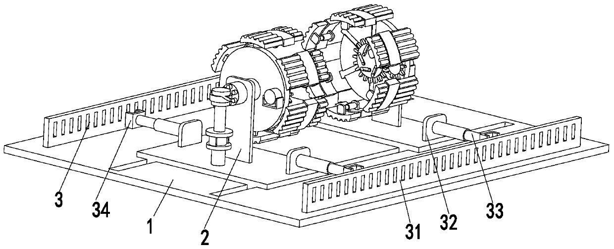
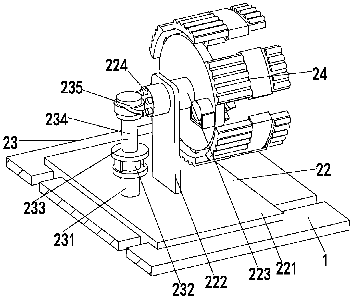
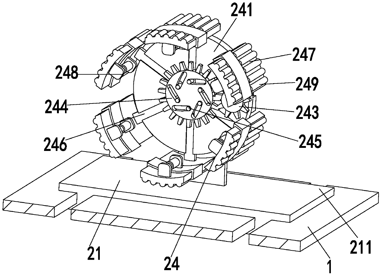
[0023] Such as Figure 1 to Figure 4 As shown, a ring-shaped workpiece clamping device for electric discharge machine tools, including a base plate 1, a clamping device 2 and a limit device 3, a chute is opened on the base plate 1, and a clamping device 2 is installed in the chute , the front and rear ends of the clamping device 2 are symmetrically arranged with the limit device 3, and the limit device 3 is installed on the bottom plate 1; wherein:

[0024]The clamping device 2 includes No. 1 moving mechanism 21, No. 2 moving mechanism 22, rotating mechanism 23 and clamping mechanism 24. No. 1 moving mechanism 21 is installed on the left side of the chute, and No. 2 moving mechanism 22 is installed on the right side of the chute. side, the uppe...


PUM


Abstract

The invention relates to annular workpiece clamping equipment for an electrical discharge machine tool. The annular workpiece clamping equipment comprises a bottom plate, a clamping device and limiting devices, wherein a sliding chute is formed in the bottom plate, the clamping device is installed in the sliding chute, the limiting devices are symmetrically arranged at the front end and the rear end of the clamping device, and the limiting devices are mounted on the bottom plate; the clamping device comprises a first moving mechanism, a second moving mechanism, a rotating mechanism and a clamping mechanism; each limiting device comprises a limiting plate, limiting supporting plates, limiting air cylinders and limiting frames; and the clamping mechanism comprises a circular working plate, arotating motor, a driving gear, a driven gear, adjusting columns, moving plates, fixed clamping plates, telescopic clamping plates and rubber strips. The annular workpiece clamping equipment can solve the problems of poor working stability, a small use range and poor adjustability existing in the clamping process of existing workpieces, can realize the function of automatically clamping the annular workpieces, and has the beneficial effects of being high in working stability, wide in use range, flexible to adjust and the like.

Description

technical field [0001] The invention relates to the field of fixture equipment, in particular to an annular workpiece clamping equipment for electric discharge machine tools. Background technique [0002] EDM machine tool, also known as CNC EDM machine tool, EDM, spark machine, etc., is a kind of electrical processing equipment. When the Lazarinko couple in the former Soviet Union studied the phenomenon and causes of the damage of the switch contacts by spark discharge corrosion, they found that the instantaneous high temperature of the electric spark could melt and oxidize the local metal and be corroded, thus creating and inventing the electric discharge machining method . When processing a workpiece on a machine tool, in order to make the surface of the workpiece meet the technical requirements such as the size, geometric shape, and mutual position accuracy with other surfaces specified in the drawing, the workpiece must be installed (positioned) and clamped (clamped) be...

Claims


Application Information

Patent Timeline
Patent Type & Authority Patents(China)
IPC IPC(8): B23H11/00
CPCB23H1/00B23H11/003
Inventor 李鸿梁荣
Owner 营口凌海精密机械制造有限公司
Why Eureka
Try Eureka