Eureka AIR delivers breakthrough ideas for toughest innovation challenges, trusted by R&D personnel around the world.

Novel yarn feeding mechanism and application thereof

A yarn feeding mechanism and yarn feeding technology, applied in textiles and papermaking, weft knitting, knitting, etc., can solve the problems of technical talents, high technical requirements, and cumbersome operations in fabric production companies, so as to facilitate maintenance and reduce Technical requirements, the effect of ensuring the original precision

Pending Publication Date: 2021-09-07
泉州精镁科技有限公司
View PDF7 Cites 0 Cited by
  • Summary
  • Abstract
  • Description
  • Claims
  • Application Information

AI Technical Summary

Problems solved by technology

When the customer adjusts the length of the fabric surface and the specification of the yarn feeding nylon gear does not meet the requirements, it may be necessary to replace the nylon gear directly linked to the yarn feeding shaft of the loom. Since the nylon gear is set in the side cover of the loom, When replacing, it is necessary to take out the entire yarn feeding bearing seat and side cover for replacement. The operation is cumbersome. The gap between the nylon gears is not more than 0.03mm, and the installation operation has relatively high technical requirements for the technicians themselves, which brings difficulties for the technical personnel of the fabric production company.

Method used

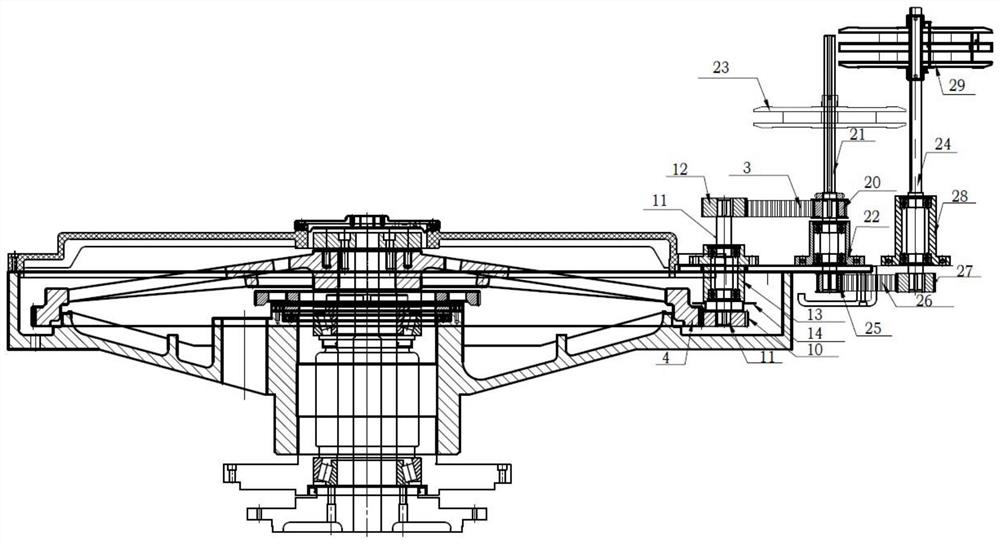
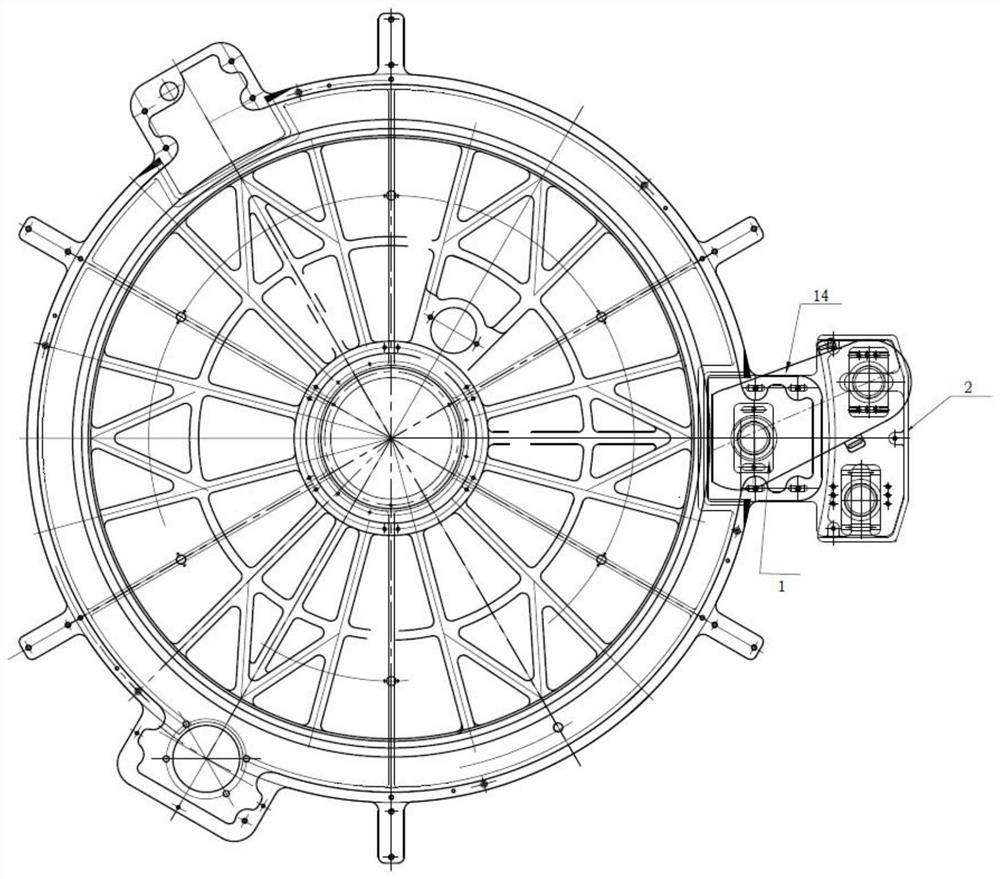
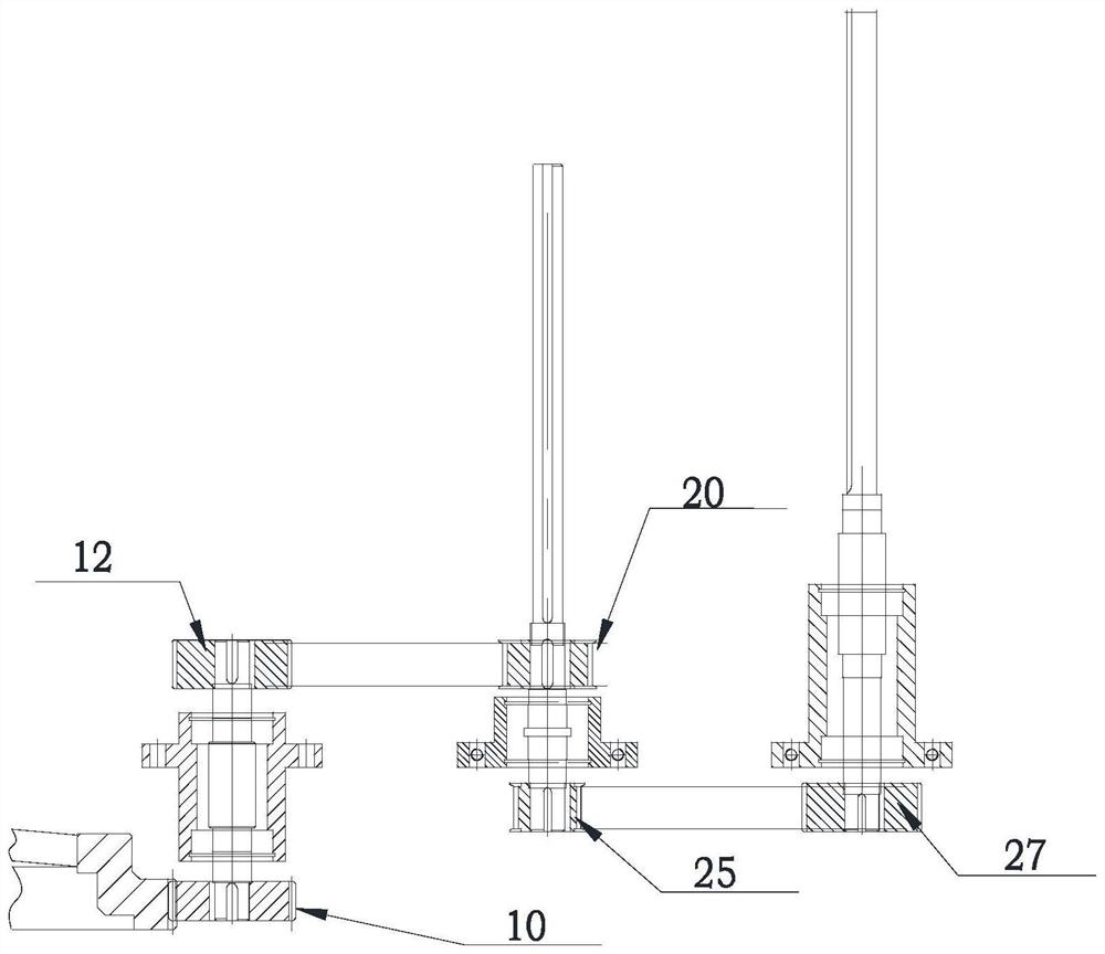

Image

  • Novel yarn feeding mechanism and application thereof
  • Novel yarn feeding mechanism and application thereof
  • Novel yarn feeding mechanism and application thereof

Examples


Embodiment 1

[0028] As a first aspect of the embodiment, a novel yarn feeding mechanism is proposed, such as Figure 1-2 As shown, it includes a fixed transmission assembly 1, a yarn feeding assembly 2, and a first connection assembly 3 that is in transmission connection with the fixed transmission assembly 1 and the yarn feeding assembly 2; wherein,

[0029] The fixed transmission assembly 1 includes a nylon gear 10 connected with the big tripod gear 4 of the circular weft knitting machine and a first synchronous gear 12 connected with the transmission of the first connection assembly 3, the nylon gear 10 and the first synchronous gear The gear 12 is connected through the yarn feeding transmission shaft 11, and the yarn feeding transmission shaft 11 is fixed on the circular weft knitting machine through the yarn feeding transmission bearing seat 13;

[0030] The first connecting component 3 is a synchronous belt;

[0031] The yarn feeding assembly 2 includes a second synchronous gear 20 ...

Embodiment 2

[0044] This embodiment presents a new type of yarn feeding structure with a single yarn feeding shaft: it includes a fixed transmission assembly 1, a yarn feeding assembly 2 and a first connecting assembly that is in transmission connection with the fixed transmission assembly 1 and the yarn feeding assembly 2 3; among them,

[0045] The fixed transmission assembly 1 includes a nylon gear 10 connected with the big tripod gear 4 of the circular weft knitting machine and a first synchronous gear 12 connected with the transmission of the first connection assembly 3, the nylon gear 10 and the first synchronous gear The gear 12 is connected through the yarn feeding transmission shaft 11, and the yarn feeding transmission shaft 11 is fixed on the circular weft knitting machine through the yarn feeding transmission bearing seat 13;

[0046] The first connecting component 3 is a synchronous belt;

[0047] The yarn feeding assembly 2 includes a second synchronous gear 20 connected to ...


PUM


Abstract

The invention relates to the field of knitting machinery, in particular to a novel yarn feeding mechanism and application thereof. The novel yarn feeding mechanism comprises a fixed transmission assembly, a yarn feeding assembly and a first connecting assembly, wherein the fixed transmission assembly comprises a nylon gear connected with a big tripod gear of a circular weft knitting machine and a first synchronous gear in transmission connection with the first connecting assembly; the nylon gear and the first synchronous gear are connected through a yarn feeding transmission shaft; the yarn feeding transmission shaft is fixed to the circular weft knitting machine through a yarn feeding transmission bearing seat; the first connecting assembly is a synchronous belt; the yarn feeding assembly comprises a second synchronous gear connected with the first connecting assembly; the synchronous gear is connected to a yarn feeding spindle B; the lower end of the yarn feeding spindle B is fixedly installed on the circular weft knitting machine through a yarn feeding shaft seat B; and the upper end of the yarn feeding spindle B is connected with a first yarn feeding aluminum disc. The fixed transmission assembly is additionally arranged, and a yarn gear is led out of a weaving machine to be installed, so that the precision of a yarn feeding part of a machine table can be better guaranteed, and the operation is more convenient.

Description

technical field [0001] The invention relates to the field of knitting machinery, in particular to a novel yarn feeding mechanism and its application. Background technique [0002] The existing yarn feeding structure is mainly that the long yarn feeding mandrel and the short yarn feeding mandrel are installed on the auxiliary foot of the circular weft knitting machine, and the rotation of the yarn feeding mandrel is driven by the big tripod gear transmission of the loom to realize the yarn feeding . When the customer adjusts the length of the fabric surface and the specification of the yarn feeding nylon gear does not meet the requirements, it may be necessary to replace the nylon gear directly linked to the yarn feeding shaft of the loom. Since the nylon gear is set in the side cover of the loom, When replacing, it is necessary to take out the entire yarn feeding bearing seat and side cover for replacement. The operation is cumbersome. The gap between the nylon gears is no...

Claims


Application Information

Patent Timeline
IPC IPC(8): D04B15/48
CPCD04B15/488
Inventor 周正二
Owner 泉州精镁科技有限公司
Why Eureka
Eureka Blog
Learn More