Cleaning equipment for electric fan protection cover

A technology for cleaning equipment and protective covers, applied in lighting and heating equipment, cleaning methods using tools, cleaning methods and utensils, etc., can solve problems such as large operation volume and hidden safety hazards.

Inactive Publication Date: 2021-09-10
江西腾世优新能源有限公司
View PDF0 Cites 2 Cited by
  • Summary
  • Abstract
  • Description
  • Claims
  • Application Information

AI Technical Summary

Problems solved by technology

[0004] In order to overcome the disadvantages of manually dismantling the protective cover and putting it in clean water for cleaning, which requires a large amount of operation and will cause safety hazards during manual cl

Method used


Image

  • Cleaning equipment for electric fan protection cover
  • Cleaning equipment for electric fan protection cover
  • Cleaning equipment for electric fan protection cover

Examples


Embodiment 1

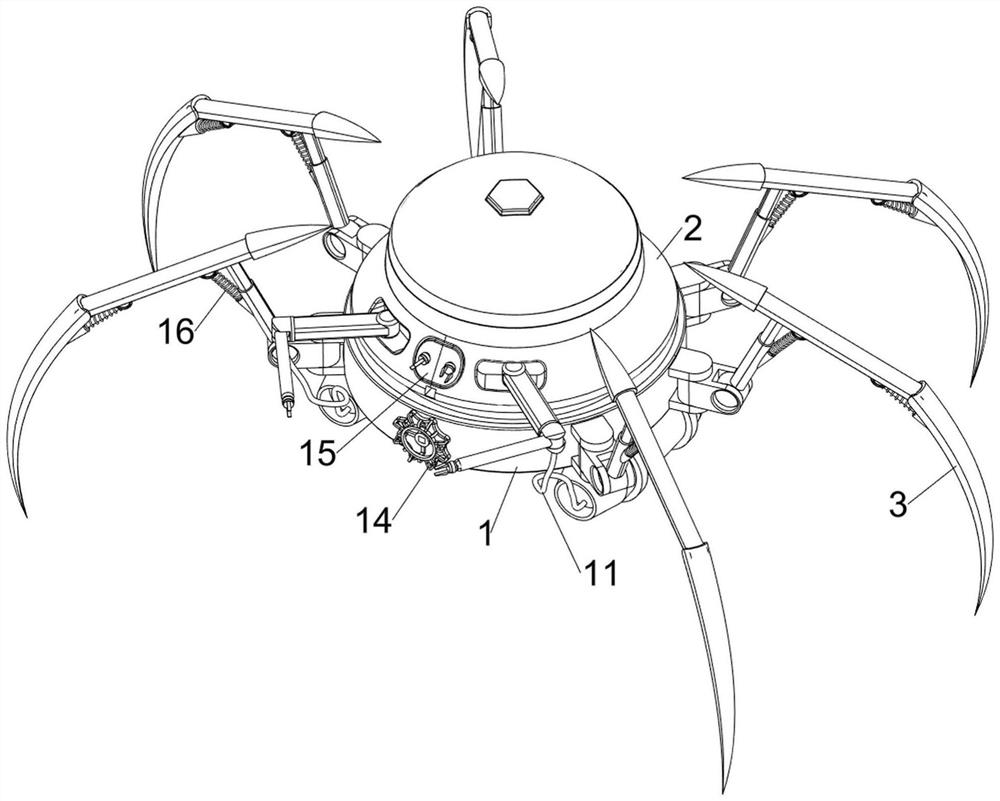
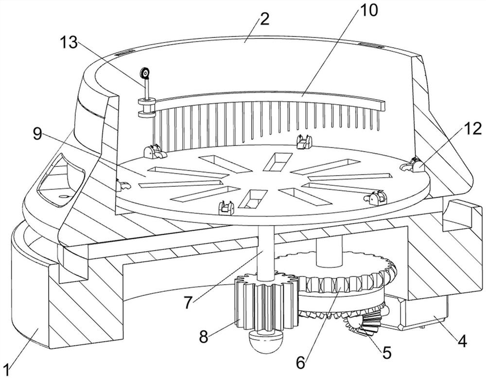
[0028] A kind of cleaning equipment for electric fan protection cover, such as Figure 1 to Figure 4 As shown, it includes a base 1, a cleaning chamber 2, a foot 3, a servo motor 4, a first bevel gear set 5, a first gear 6, a first rotating shaft 7, a second gear 8, a turntable 9, a cleaning assembly 10 and a water delivery Assembly 11, the top of the base 1 is provided with a cleaning chamber 2, and a first rotating shaft 7 is movable between the cleaning chamber 2 and the base 1, and the top of the first rotating shaft 7 is connected with a turntable 9, and the lower part of the first rotating shaft 7 is provided with a second gear 8 , the top rear side of the inner wall of the base 1 is rotatably provided with a first gear 6, the first gear 6 meshes with the second gear 8, the rear side of the base 1 is provided with a servo motor 4, the output shaft of the servo motor 4 and the rotation of the first gear 6 The first bevel gear set 5 is connected between the bottom of the s...

Embodiment 2

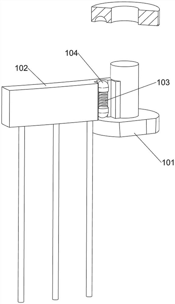
[0033] On the basis of Example 1, such as Figure 5 to Figure 8As shown, a clamping assembly 12 is also included, and the clamping assembly 12 includes a second fixed block 121, a clamping plate 122, a wedge bar 123, a button 124, a second spring 125, a block 126 and a third spring 127, and the top of the turntable 9 The outer side is evenly provided with 6 second fixed blocks 121, the outside of the second fixed block 121 is hinged with splint 122, the symmetrical sliding type is provided with wedge-shaped rod 123 on the second fixed block 121, and the top of wedge-shaped rod 123 is provided with button 124, the second The fixed block 121 inner wall is symmetrically movable and provided with a block 126, the third spring 127 is connected between the outside of the block 126 and the inner wall of the second fixed block 121, and the third spring 127 is connected between the bottom of the block 126 and the inner wall of the second fixed block 121. Two springs 125.

[0034] The ...

Embodiment 3

[0038] On the basis of Example 2, such as Figure 9 to Figure 11 As shown, it also includes a lifting assembly 14, and the lifting assembly 14 includes a screw mandrel 141, a nut 142, a connecting rod 143, a third bevel gear set 144, a rotating rod 145 and a knob 146. Screw mandrel 141, threaded screw mandrel 141 bottom is provided with nut 142, and nut 142 rear side is provided with connecting rod 143, and connecting rod 143 rear part is positioned at the second gear 8 below and is connected with the first rotating shaft 7 rotationally, base 1 front side The rotary type is provided with a rotating rod 145, the third bevel gear set 144 is connected between the rear side of the rotating rod 145 and the top of the screw mandrel 141, and the front side of the rotating rod 145 is provided with a knob 146.

[0039] After cleaning, the staff can turn the knob 146 to drive the third bevel gear set 144 to rotate through the rotating rod 145, the third bevel gear set 144 rotates throug...


PUM


Abstract

The invention relates to cleaning equipment, in particular to cleaning equipment for an electric fan protection cover. According to the cleaning equipment for the electric fan protection cover, manual cleaning is not needed, safety failures are prevented during cleaning, and the cleaning quality is guaranteed. The cleaning equipment for the electric fan protection cover comprises a base, a cleaning bin, a first gear, a first rotating shaft, a second gear and a rotary table, the cleaning bin is arranged at the top of the base, the first rotating shaft is movably arranged between the cleaning bin and the base, the rotary table is connected to the top of the first rotating shaft, the second gear is arranged on the lower portion of the first rotating shaft, the first gear is rotationally arranged on one side of the top of the inner wall of the base, and the first gear is engaged with the second gear. By arranging a cleaning assembly and a water conveying assembly, the protection cover is driven to rotate and makes contact with a brush at the same time, so that the protection cover is cleaned, and the basic functions of the equipment are achieved.

Description

technical field [0001] The invention relates to a cleaning device, in particular to a cleaning device for an electric fan protective cover. Background technique [0002] Electric fans are common household electrical appliances in people's daily life. Whenever summer comes, electric fans are needed to cool down to meet people's daily life. However, the protective cover of the electric fan that has been placed for the whole winter will inevitably accumulate a lot of dust, and Electric fans also accumulate dust when they are in use, especially in dusty cities and rural areas, which requires cleaning the protective cover and blades of the electric fan. [0003] In the prior art, the cleaning of the protective cover of the electric fan is mainly carried out manually, and the protective cover is disassembled manually and put into clear water for cleaning. This cleaning method brings a lot of inconvenience to people's daily life, and the protective cover of the electric fan And fa...

Claims


Application Information

Patent Timeline
IPC IPC(8): B08B1/02B08B13/00F26B5/08
CPCB08B1/02B08B1/002B08B13/00F26B5/08
Inventor 彭灵
Owner 江西腾世优新能源有限公司
Why Eureka
Try Eureka