
A sealing structure for the hydraulic end plunger hole of a fracturing pump

A technology of sealing structure and plunger hole, which is applied to pump components, variable capacity pump components, liquid fuel engines, etc., can solve the problems of inability to dynamically adjust the sealing effect, poor sealing effect, and little improvement, etc. The effect of reducing relative motion, avoiding contact damage, and prolonging service life

Active Publication Date: 2022-05-13
SOUTHWEST PETROLEUM UNIV
View PDF23 Cites 0 Cited by
  • Summary
  • Abstract
  • Description
  • Claims
  • Application Information

AI Technical Summary

Problems solved by technology

[0003] For the in-hole sealing of high-pressure plunger pumps, the existing technology is relatively mature and there are many solutions. However, due to reasons such as high pressure and fracturing fluid erosion, the sealing packing sometimes still has poor sealing effect. Due to the situation, it needs to be replaced frequently, but the replacement will also have a certain impact on the stability of the installation and connection. Therefore, looking for a solution with better connection and sealing stability after replacement can effectively improve the convenience of maintenance and operation during on-site construction. The existing technology also has certain advantages. Exploration, such as the application number CN201520393494.4 "A Fracturing Pump and Fracturing Truck" provides a solution for the packing and the card slot to be pulled out together, but this solution is not too big compared with the traditional method. Improvement; the application number is CN202021577778.6 "A sealing device for hydraulic end valve box of fracturing pump with corrosion resistance" provides a scheme using multiple sealing surfaces, but this scheme also has similar problems and cannot be dynamically Adjust the sealing effect

Method used


Image

  • A sealing structure for the hydraulic end plunger hole of a fracturing pump
  • A sealing structure for the hydraulic end plunger hole of a fracturing pump
  • A sealing structure for the hydraulic end plunger hole of a fracturing pump

Examples


Embodiment Construction

[0032] The following will clearly and completely describe the technical solutions in the embodiments of the present invention with reference to the accompanying drawings in the embodiments of the present invention. Obviously, the described embodiments are only some, not all, embodiments of the present invention. Based on the embodiments of the present invention, all other embodiments obtained by persons of ordinary skill in the art without making creative efforts belong to the protection scope of the present invention.

[0033] In describing the present invention, it should be understood that the terms "center", "longitudinal", "transverse", "upper", "lower", "front", "rear", "left", "right", " The orientations or positional relationships indicated by "vertical", "horizontal", "top", "bottom", "inner", "outer", etc. are based on the orientation or positional relationship shown in the drawings, and are only for the convenience of describing the present invention and Simplified ...


PUM


Abstract

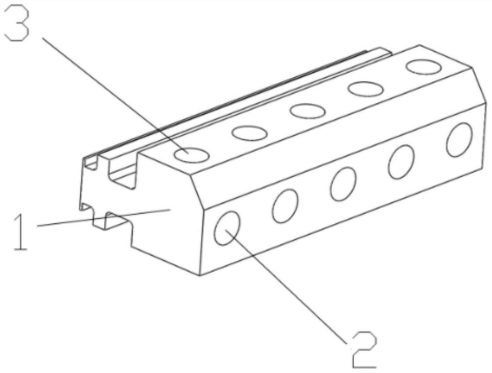
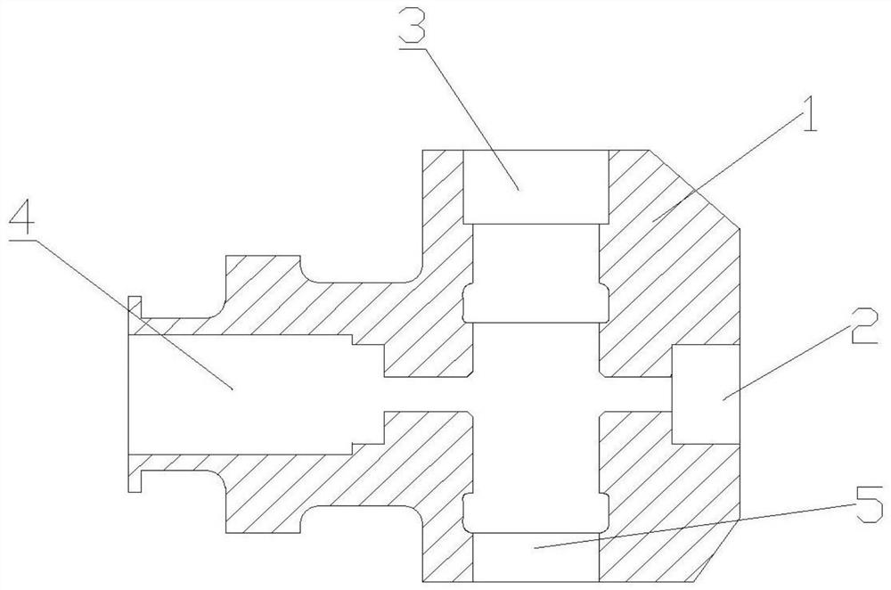
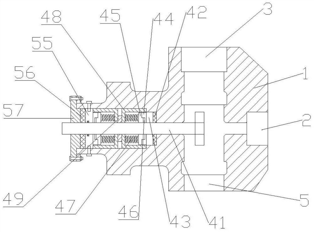
The invention discloses a sealing structure for a plunger hole of a hydraulic end of a fracturing pump, which includes a sealing mechanism arranged in the plunger hole of a valve box main body, the sealing mechanism includes two sets of seals, and two sets of seals for fixing the two sets of seals. The end cap and the shaft sleeve of the seal, the end cap and the shaft sleeve are provided with through holes, the shaft sleeve is pressed through the end cap, and the two sets of the seal are connected through the shaft sleeve Press against the plunger hole; each set of the seal includes a buffer seat, a buffer, a sliding ring, a rotating ring, and a sealing ring. The invention improves the sealing structure of the inner hole of the high-pressure plunger pump, so that the sealing member can maintain the sealing effect more stably, improves the safety factor of on-site use, and prolongs the service life.

Description

technical field [0001] The invention relates to the technical field of oil exploitation equipment, in particular to the technical field of fracturing equipment, in particular to a sealing structure for a plunger hole at the hydraulic end of a fracturing pump. Background technique [0002] In the development of oil and gas fields, fracturing technology is widely used in stimulation construction. Fracturing technology is a method of using liquid pressure to form cracks in oil and gas formations. The most important equipment in fracturing construction is high-pressure plunger pumps, which are generally composed of multiple fracturing vehicles equipped with high-pressure plunger pumps. The plunger pump set is under construction. The high-pressure plunger pump is divided into two parts: the power end and the liquid end. The power end converts the energy of the diesel engine or the motor into kinetic energy and transmits it to the liquid end through the plunger. The main componen...

Claims


Application Information

Patent Timeline
Patent Type & Authority Patents(China)
IPC IPC(8): F04B53/00F04B53/14F04B53/22E21B43/26
CPCF04B53/00F04B53/143F04B53/22E21B43/2607
Inventor 于学会王安帅曾兴昌周小明张士顺
Owner SOUTHWEST PETROLEUM UNIV
Learn More