Device for drawing longitude and latitude lines
A technology of longitude, latitude and latitude, which is applied in the direction of planetarium/globe, instruments, educational appliances, etc., and can solve the problem of drawing tools or devices that do not find the longitude and latitude of the globe
- Summary
- Abstract
- Description
- Claims
- Application Information
AI Technical Summary
Problems solved by technology
Method used
Image


Examples
Embodiment 1
[0037] Please refer to Figure 1 to Figure 5 , figure 1 Split structure front view for the present invention; figure 2 Split structure side view for the present invention; image 3 It is the front view of the combined structure of the present invention; Figure 4 It is a side view of the combined structure of the present invention; Figure 5 It is a top view of the combined structure of the present invention.
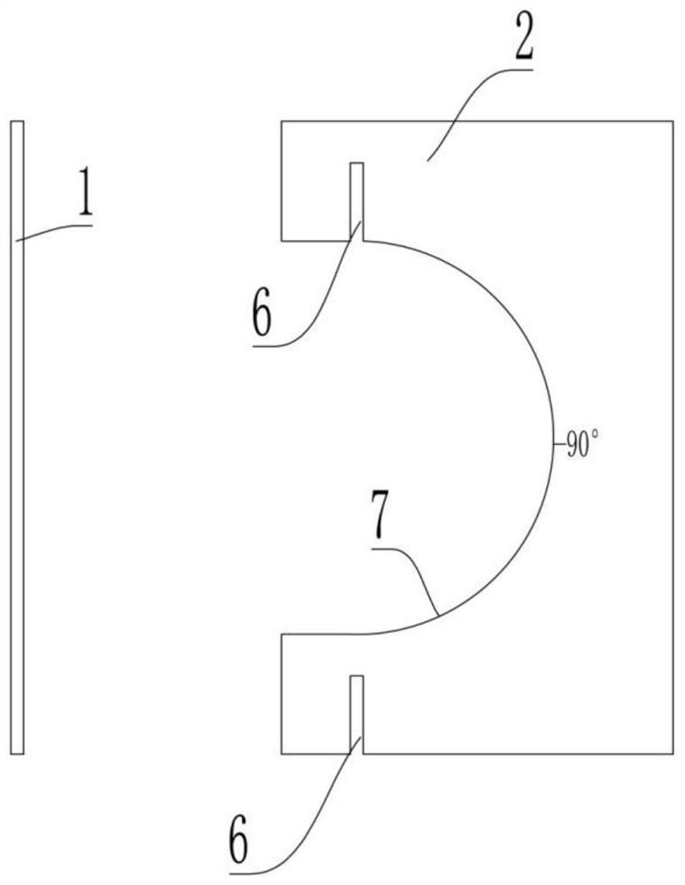
[0038] A device for drawing warp and latitude, comprising a warp drawing unit for drawing warp and a weft drawing unit for drawing weft.
[0039] When in use, the meridian can be drawn directly on the sphere 12 by the meridian drawing part, and then the latitude can be drawn on the sphere 12 by the latitude drawing part, thereby obtaining a simple globe with longitude and latitude.
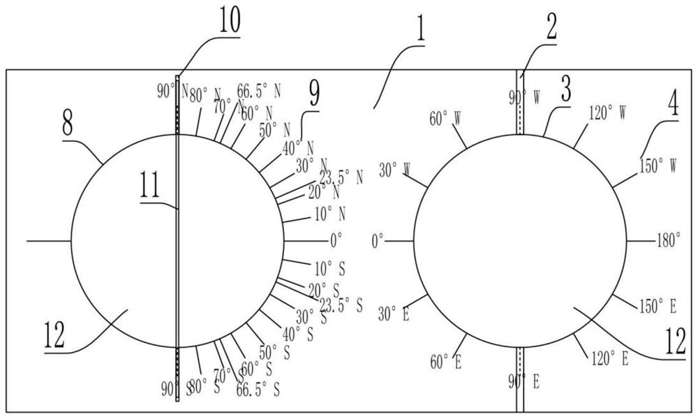
[0040]Specifically, the meridian drawing part includes a first seat body, on which a hemispherical supporting structure is arranged, and a longitude scale 4 is arranged at the circula...
Embodiment 2
[0044] Please refer to Figure 1 to Figure 5 , figure 1 Split structure front view for the present invention; figure 2 Split structure side view for the present invention; image 3 It is the front view of the combined structure of the present invention; Figure 4 It is a side view of the combined structure of the present invention; Figure 5 It is a top view of the combined structure of the present invention.
[0045] This embodiment proposes a device for drawing warp and latitude lines. Compared with the device in Embodiment 1, the main difference is that: the second seat body in this embodiment is provided with a vertical shaft rod 11, and the shaft rod 11 is connected with the latitude line. The connecting line of 90°N and 90°S drawn in hole 8 coincides.
[0046] In this embodiment, a vertical shaft rod 11 is set at the center of the parallel drawing hole 8. When drawing the parallel, the shaft rod 11 passes through the south pole and the north pole of the sphere 12, ...
Embodiment 3
[0049] Please refer to Figure 1 to Figure 5 , figure 1 Split structure front view for the present invention; figure 2 Split structure side view for the present invention; image 3 It is the front view of the combined structure of the present invention; Figure 4 It is a side view of the combined structure of the present invention; Figure 5 It is a top view of the combined structure of the present invention.
[0050] This embodiment proposes a device for drawing latitude and longitude lines. Compared with the device in Embodiment 2, the main difference is that: the above-mentioned second base body in this embodiment is provided with a card slot 10 that is engaged with the shaft rod 11 , the card slot 10 is located at the upper end and / or lower end of the weft thread drawing hole 8 .
[0051] In this embodiment, the number of draw-in slots 10 is two, which are located at the upper and lower ends of the weft-drawing holes 8 respectively, and coincide with the connecting l...
PUM
 Abstract
Description
Claims
Application Information