New energy automobile battery bundling and locking device

A new energy vehicle and locking device technology, which is applied to battery pack components, circuits, electrical components, etc., can solve the problems of easy change in the size of new energy batteries, cumbersome operation, and inconvenient fixing of new energy batteries

Inactive Publication Date: 2021-09-10
邓宏朝
View PDF0 Cites 4 Cited by
  • Summary
  • Abstract
  • Description
  • Claims
  • Application Information

AI Technical Summary

Problems solved by technology

[0005] The purpose of the present invention is to provide a new energy vehicle battery binding and locking device in order to solve the above problems, so as to solve the problem that in the prior art, when the new energy battery is fixed, the new energy battery is usually fixed by bolts. It is not convenient enough to disassemble and disassemble, a waste of time and energy, and because the replacement speed of new energy batteries is relatively fast, the size of new energy batteries is prone to change during the replacement process, and it is not convenient to fix new energy batteries. When picking up the battery, drag out the new energy battery from the inside of the battery compartment. Due to the narrow space inside the battery compartment, you need to use tools to take out the new energy battery. The operation is cumbersome, wasting time and manpower.

Method used


Image

  • New energy automobile battery bundling and locking device
  • New energy automobile battery bundling and locking device
  • New energy automobile battery bundling and locking device

Examples


Embodiment Construction

[0030] An embodiment of the present invention provides a new energy vehicle battery binding and locking device.

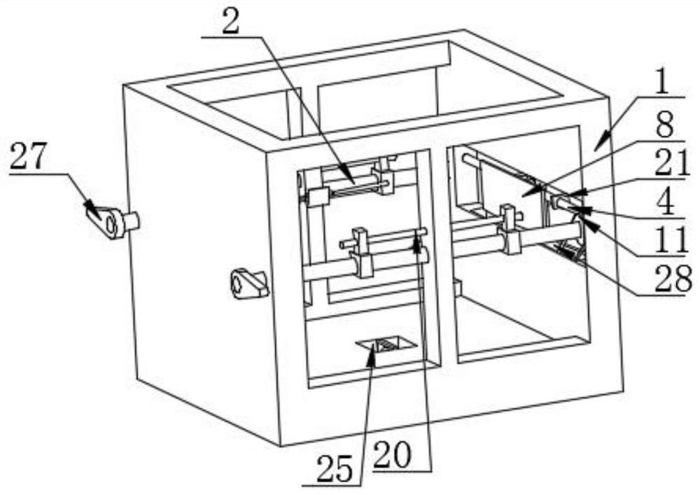
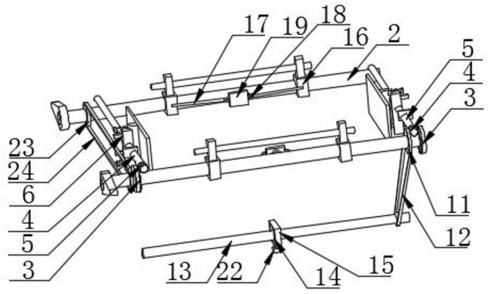
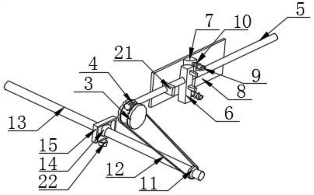
[0031] see figure 1 , figure 2 , image 3 , Figure 4 , Figure 5 , Figure 6 and Figure 7 , including a fixed frame 1, and a fixed component is arranged inside the fixed frame 1;

[0032] The fixing assembly includes two first screw rods 2, both of which run through the fixed frame 1 and are connected to the fixed frame 1 in rotation, and the outer sides of the two first screw rods 2 are fixedly connected with a first bevel gear 3, and the second One side of the bevel gear 3 is engaged with the second bevel gear 4, and one side of the second bevel gear 4 is fixedly connected with the second screw mandrel 5. 6 is slidably connected to the inside of the fixed frame 1, a second bump 7 is provided on one side of the first bump 6, the sides of the first bump 6 and the second bump 7 are both set as arc surfaces, and the side of the second bump 7 is The limitin...


PUM


Abstract

The invention provides a new energy automobile battery bundling and locking device, and relates to the technical field of new energy automobiles. The new energy automobile battery bundling and locking device comprises a fixing frame, a fixing assembly is arranged in the fixing frame, the fixing assembly comprises two first lead screws, the two first lead screws penetrate through the fixing frame and are rotationally connected with the fixing frame, first bevel gears are fixedly connected to the outer sides of the two first lead screws, one side of each first bevel gear is in engaged connection with a second bevel gear. According to the new energy automobile battery bundling and locking device, the second bevel gears rotate to drive second lead screws to rotate, the second lead screws rotate to drive first protruding blocks to move rightwards, the first protruding blocks move rightwards to extrude second protruding blocks to move outwards, the second protruding blocks move outwards to drive limiting plates to move outwards, so that a new energy battery is fixed; With the above structure adopted, new energy batteries with different sizes can be quickly fixed. The device is simple in structure, convenient to operate, time-saving and labor-saving.

Description

technical field [0001] The invention relates to a locking device, in particular to a new energy vehicle battery binding locking device, which belongs to the technical field of new energy vehicles. Background technique [0002] The battery capacity of electric vehicles is limited, and its mileage is still very limited, which requires setting up charging stations on the road, but the charging time of batteries is generally longer, which will be difficult for car users, especially buses that mainly carry passengers. Very unfavorable, it not only delays the driver's time but also may delay the passenger's journey. A more feasible method is to reserve batteries with sufficient power at each charging station, or carry a spare battery with the car. The car that needs to be charged only needs to replace the battery at the charging station or by itself to continue moving forward, which will greatly save charging time. New energy vehicles refer to vehicles that use unconventional veh...

Claims


Application Information

Patent Timeline
Patent Type & Authority Applications(China)
IPC IPC(8): H01M50/244H01M50/264H01M50/249H01M50/242
CPCH01M50/244H01M50/264H01M50/249H01M50/242Y02E60/10
Inventor 邓宏朝
Owner 邓宏朝
Why Eureka
Try Eureka