
Mine stone loading and unloading equipment and using method thereof

A technology for loading and unloading equipment and stones, which is applied in the direction of cleaning methods using liquids, cleaning methods using tools, loading/unloading, etc., and can solve the problems of increasing the difficulty of the work of the staff, poor practicability, and affecting work efficiency, etc.

Pending Publication Date: 2021-09-14
孙帮营
View PDF1 Cites 1 Cited by
  • Summary
  • Abstract
  • Description
  • Claims
  • Application Information

AI Technical Summary

Problems solved by technology

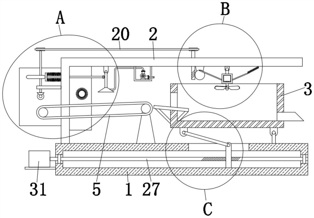
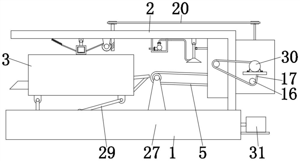
[0003] After retrieval, the prior art (application number: CN201921893608.6) discloses a mining raw material transportation equipment. The inventor found the following problems while realizing the prior art: 1. The device transports stone materials The lack of the function of cleaning the stone in the process, resulting in the problem that there are more impurities attached to the outside of the stone; 2. In addition, it is difficult to quickly air-dry the stone after spraying the stone in the prior art, which affects the corresponding work. Work efficiency; 3. In addition, the existing technology generally requires manpower to dump stones to a certain extent, which increases the work difficulty of the corresponding staff and has poor practicability. Therefore, we propose a mine stone loading and unloading equipment and its use method for solve the above problems

Method used


Image

  • Mine stone loading and unloading equipment and using method thereof
  • Mine stone loading and unloading equipment and using method thereof
  • Mine stone loading and unloading equipment and using method thereof

Examples


Embodiment Construction

[0028] The following will clearly and completely describe the technical solutions in the embodiments of the present invention with reference to the accompanying drawings in the embodiments of the present invention. Obviously, the described embodiments are only some, not all, embodiments of the present invention.

[0029] In describing the present invention, it should be understood that the terms "upper", "lower", "front", "rear", "left", "right", "top", "bottom", "inner", " The orientation or positional relationship indicated by "outside", etc. is based on the orientation or positional relationship shown in the drawings, and is only for the convenience of describing the present invention and simplifying the description, rather than indicating or implying that the referred device or element must have a specific orientation, so as to Specific orientation configurations and operations, therefore, are not to be construed as limitations on the invention.

[0030] refer to Figure ...


PUM


Abstract

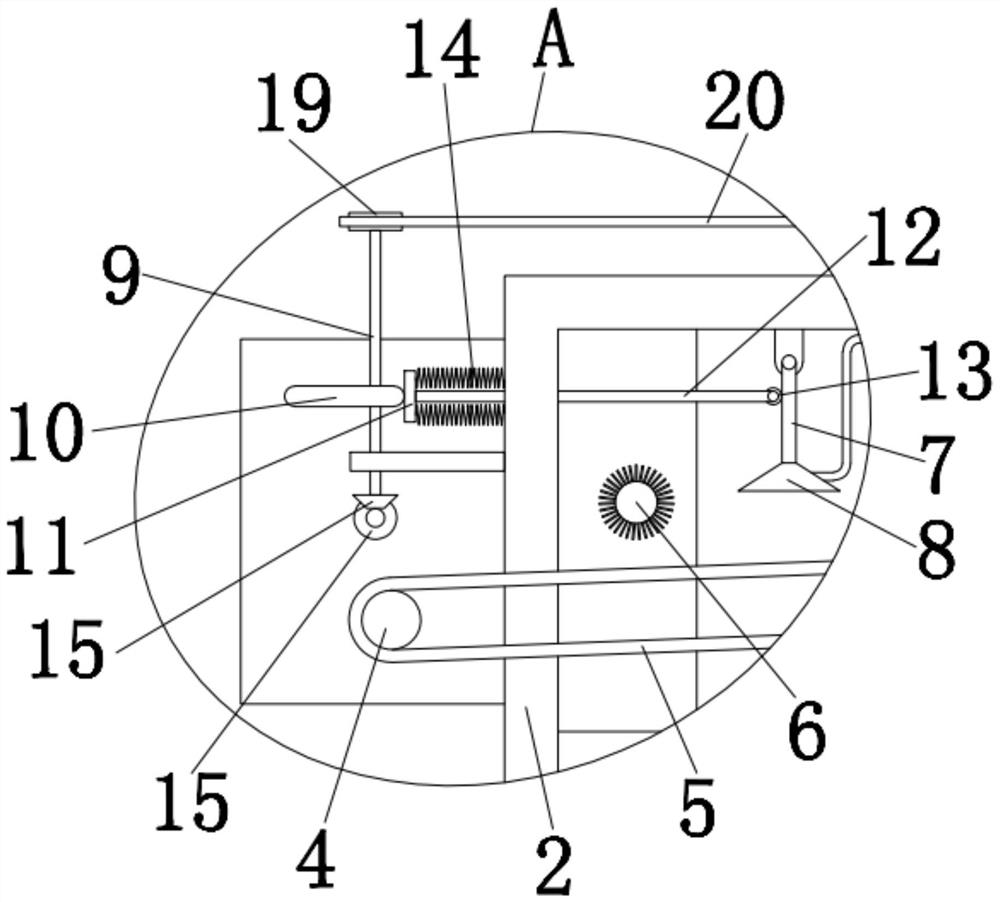
The invention relates to the technical field of loading and unloading equipment, and discloses mine stone loading and unloading equipment and a using method thereof. The mine stone loading and unloading equipment comprises a base, an L-shaped supporting rod is fixedly installed on one side of the top of the base, and a storage frame is rotationally installed on the other side of the top of the base. Conveying wheels are rotationally mounted on the top of the base and the outer side of the L-shaped supporting rod, the two conveying wheels are in transmission connection with the same conveying belt, a cleaning wheel is rotationally mounted on the inner side of the L-shaped supporting rod, a swing rod is rotationally mounted on the top of the inner side of the L-shaped supporting rod, a spray head is fixedly mounted at the bottom end of the swing rod, and a vertical shaft is rotationally mounted at the top of the outer side of the L-shaped supporting rod. The mine stone loading and unloading equipment is reasonable in design, stone can be cleaned in the stone conveying process, so that the cleanliness of the stone is guaranteed, a swing frame synchronously swings through rotation of a worm wheel, fan blades are driven to swing, the air blowing range of the fan blades can be enlarged, and the air drying efficiency of the stone is improved.

Description

technical field [0001] The invention relates to the technical field of loading and unloading equipment, in particular to a mine stone loading and unloading equipment and a method for using the same. Background technique [0002] Mine refers to an independent production and operation unit that extracts ore with a certain mining boundary. Mine mainly includes one or more mining workshops (or called pitheads, mine shafts, open-pit stopes, etc.) and some auxiliary workshops. Most mines also include beneficiation plants. Stone materials are sand and gravel permeable materials from the perspective of water permeability. The bridge buildings in the road and stone production line are not only affected by the complex force system of the vehicle load, but also by various complex natural factors. Therefore, the materials used for construction and bridges must not only have certain mechanical properties, At the same time, it must have the durability that does not produce obvious streng...

Claims


Application Information

Patent Timeline
IPC IPC(8): B65G69/20B65G65/23B08B1/04B08B1/02B08B3/02
CPCB65G69/20B65G65/23B08B3/022B08B1/20B08B1/32
Inventor 孙帮营
Owner 孙帮营
Learn More