
Concrete vertical lifting device for chimney construction

A vertical lifting and concrete technology, which is applied in the processing of building materials, construction, building structure, etc., can solve the problems of easy breakage, not enough practicality, and inability to adjust the concrete lifting device.

Active Publication Date: 2021-09-14
江苏新大高空工程有限公司
View PDF7 Cites 0 Cited by
  • Summary
  • Abstract
  • Description
  • Claims
  • Application Information

AI Technical Summary

Problems solved by technology

[0004] The purpose of the present invention is to provide a concrete vertical lifting device for chimney construction, to solve the problem that the conveying height of the existing concrete vertical lifting device proposed in the above-mentioned background technology is relatively fixed, and usually only chimneys of a specific height can be built, so that the existing The concrete lifting device cannot be adjusted according to actual use requirements, and it has certain limitations in use. In order to facilitate the adjustment of the position, the existing concrete vertical lifting device usually uses a soft rubber tube as the delivery pipe, but the concrete has a high density and a large lift. As a result, the conveying pipeline is subjected to extremely high pressure when conveying concrete, and the soft rubber pipe is easily damaged under this pressure for a long time, and the adaptable life is short, which increases the cost of the existing concrete vertical lifting device and is not practical enough to use

Method used


Image

  • Concrete vertical lifting device for chimney construction
  • Concrete vertical lifting device for chimney construction
  • Concrete vertical lifting device for chimney construction

Examples


Embodiment Construction

[0037] The following will clearly and completely describe the technical solutions in the embodiments of the present invention with reference to the accompanying drawings in the embodiments of the present invention. Obviously, the described embodiments are only some, not all, embodiments of the present invention. Based on the embodiments of the present invention, all other embodiments obtained by persons of ordinary skill in the art without making creative efforts belong to the protection scope of the present invention.

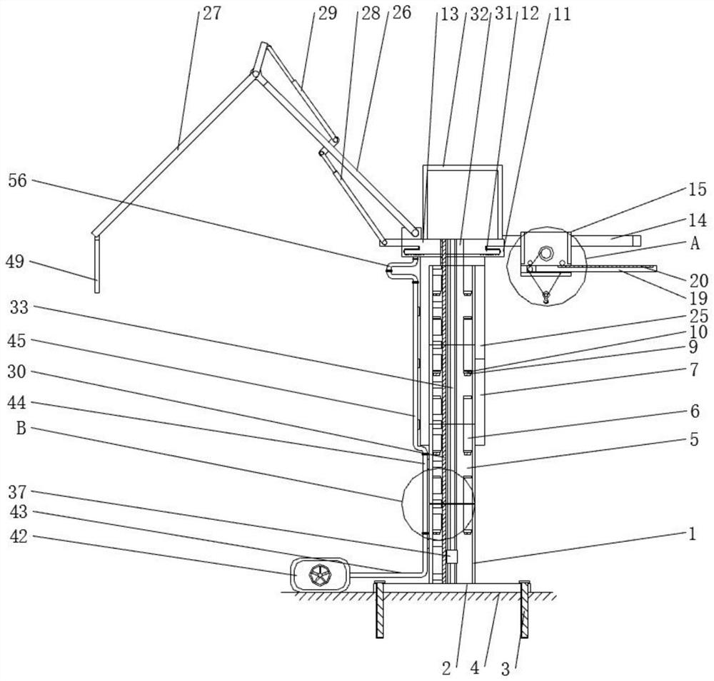
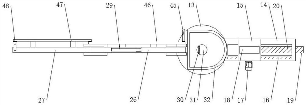
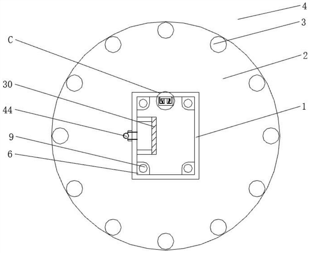
[0038] see Figure 1-11 , the present invention provides a technical solution: a concrete vertical lifting device for chimney construction, such as figure 1 , image 3 and Figure 10 As shown, the bottom of the fixed hanger 1 is welded and fixed with a base 2, and the base 2 is fixedly installed on the upper surface of the ground 4 through embedded bolts 3, and a plurality of extension hangers 5 are sequentially installed on the top of the fixed hanger 1, an...


PUM


Abstract

The invention discloses a concrete vertical lifting device for chimney construction. The concrete vertical lifting device comprises a fixed hanging bracket, a fixed table, a first cantilever, a crawling ladder, a concrete piston pump and a third hydraulic driving device, a base is fixedly welded to the bottom of the fixed hanging bracket, and the base is fixedly installed on the upper surface of the ground through embedded bolts; and a plurality of extending hanging brackets are sequentially installed at the top of the fixed hanging bracket, and connecting sleeves are fixedly welded to the upper side in the fixed hanging bracket and the upper sides and the lower sides in the extending hanging brackets. The concrete vertical lifting device for chimney construction is provided with a sliding frame, a first rack and a first driving device, when the positions of the first cantilever and the second cantilever are adjusted, the first driving device is matched with the first rack to push a sliding table to slide along the sliding frame, the position of the balance weight can be conveniently adjusted in real time according to the operation state of the vertical concrete lifting device, the balance weight can be hoisted on a lifting hook, the balance weight effect is further improved, and the stability of the concrete vertical lifting device for chimney construction is greatly improved.

Description

technical field [0001] The invention relates to the technical field of concrete vertical lifting devices, in particular to a concrete vertical lifting device for chimney construction. Background technique [0002] When building a high-rise concrete chimney, in order to quickly transport a large amount of concrete from the ground to the high-level steel skeleton, it is necessary to use a concrete vertical lifting device. [0003] The conveying height of the existing concrete vertical lifting device is relatively fixed, and usually only a chimney of a specific height can be built, so that the existing concrete lifting device cannot be adjusted according to actual use requirements, and has certain limitations in use. The existing concrete vertical In order to facilitate the adjustment of the position of the lifting device, a soft rubber tube is usually used as the conveying pipe, but the density of the concrete is high and the head is large, so that the conveying pipe bears gre...

Claims


Application Information

Patent Timeline
IPC IPC(8): E04G21/02
CPCE04G21/02
Inventor 王维王成
Owner 江苏新大高空工程有限公司
Learn More