
Device and method for positioning fault in transformer shell

A technology of transformer housing and positioning device, applied in transformer testing, measuring device, measuring device shell, etc., can solve the problems of error, inability to collect direct wave partial discharge signal, affecting positioning accuracy, etc.

Pending Publication Date: 2021-09-14
DALI BUREAU OF ULTRA HIGH VOLTAGE TRANSMISSION CO CHINA SOUTHERN POWER GRID CO LTD
View PDF0 Cites 0 Cited by
  • Summary
  • Abstract
  • Description
  • Claims
  • Application Information

AI Technical Summary

Problems solved by technology

[0002] At present, most of the ultrasonic localization methods for transformer vibration sources at home and abroad regard the transformer as a box filled with oil, without considering the influence of the transformer internal structure and the metal box wall on the propagation path and propagation velocity of the ultrasonic signal. If only a fixed propagation velocity is used To calculate the position of the PD source will seriously affect the positioning accuracy
In addition, when the ultrasonic signal propagates to the metal shell, due to the total reflection, when the incident angle exceeds the total reflection angle, the sensor will not be able to collect the partial discharge signal from the direct wave at this time, if the ultrasonic direct wave path is still used in this case If it is calculated, it will introduce a huge error, and it is difficult to accurately judge the location of the partial discharge source

Method used


Image

  • Device and method for positioning fault in transformer shell
  • Device and method for positioning fault in transformer shell
  • Device and method for positioning fault in transformer shell

Examples


Embodiment Construction

[0036] In order to make the objectives, technical solutions and advantages of the present application clearer, the technical solutions of the present application will be clearly and completely described below with reference to the specific embodiments of the present application and the corresponding drawings. Obviously, the described embodiments are only a part of the embodiments of the present application, but not all of the embodiments. Based on the embodiments in the present application, all other embodiments obtained by those of ordinary skill in the art without creative efforts shall fall within the protection scope of the present application.

[0037] The technical solutions provided by the embodiments of the present application will be described in detail below with reference to the accompanying drawings.

[0038] At present, there are two main types of fault detection methods in the transformer casing commonly used in the market: the acceleration sensor method outside ...


PUM


Abstract

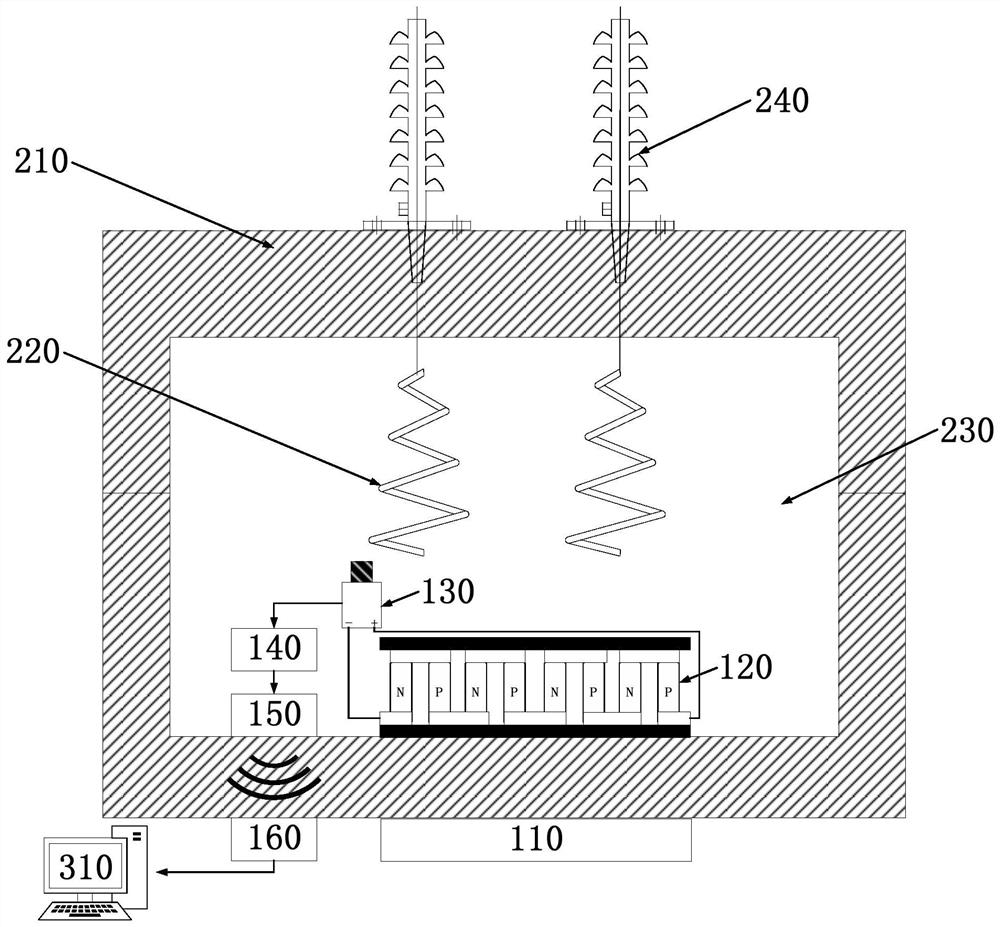
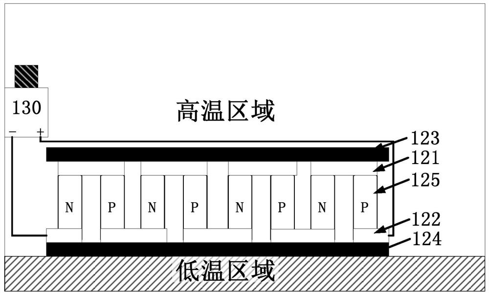
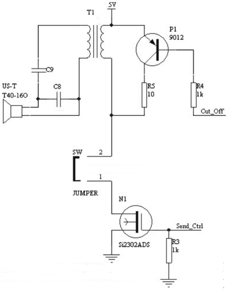
The invention provides a device and a method for positioning a fault in a transformer shell. The device comprises a refrigeration sheet, a thermoelectric power generation unit, a plurality of vibration sensors, and an ultrasonic wave transmission module. The refrigeration sheet is installed at the outer side of the shell of a transformer; the thermoelectric power generation unit is mounted on the inner side of the shell of the transformer and is opposite to the refrigeration sheet in position; the plurality of vibration sensors are installed in the transformer, the optimal arrangement scheme of the vibration sensors in insulating oil is determined according to a sensor optimal configuration model, and the vibration sensors are used for detecting and positioning the vibration condition in the transformer in a plurality of different directions in the insulating oil; the plurality of vibration sensors are connected with the thermoelectric power generation unit so as to be powered by the thermoelectric power generation unit; and the ultrasonic wave transmission module is used for sending the vibration condition and the positioning information in the transformer to a terminal outside the transformer. According to the invention, the positioning of a fault source is achieved, the fault measurement precision is higher, and richer information is reflected.

Description

technical field [0001] The application relates to the technical field of measurement equipment, and in particular, to a device and method for locating faults in a transformer casing. Background technique [0002] At present, most of the ultrasonic positioning methods of transformer vibration source proposed at home and abroad regard the transformer as a box filled with oil, and do not consider the influence of the inner structure of the transformer and the metal box wall on the propagation path and propagation speed of the ultrasonic signal. If only a fixed propagation speed is used To calculate the position of the PD source will seriously affect the positioning accuracy. In addition, when the ultrasonic signal propagates to the metal casing, due to the total reflection, when the incident angle exceeds the total reflection angle, the sensor will not be able to collect the partial discharge signal from the direct wave. In this case, the ultrasonic direct wave path is still us...

Claims


Application Information

Patent Timeline
Patent Type & Authority Applications(China)
IPC IPC(8): G01R31/12G01R31/62G01R1/04G01H17/00
CPCG01R31/1263G01R31/1209G01R31/62G01R1/0408G01H17/00
Inventor 王鹏飞崔学龙吴华丰李浩丹杜庆贤于刚干强程佳路
Owner DALI BUREAU OF ULTRA HIGH VOLTAGE TRANSMISSION CO CHINA SOUTHERN POWER GRID CO LTD
Learn More