Automatic control, detection, protection and cleaning system for power transmission line

A technology of transmission lines and detection loops, applied in electric vehicles, circuit devices, battery circuit devices, etc., can solve the problems of urban power system failure, easy adhesion of garbage, and cumbersome cleaning.

Active Publication Date: 2021-09-14
许昌皓硕环保科技有限公司
View PDF14 Cites 2 Cited by
  • Summary
  • Abstract
  • Description
  • Claims
  • Application Information

AI Technical Summary

Problems solved by technology

[0002] The transmission line is an important part used for power transmission from the power station to the user unit. Whether it is in the city or in the field, many transmission lines will be erected for power transmission; Such as bird droppings, balloon leads, kite wires, plastic bags, etc., and in some cold regions, the surface of the transmission line is more likely to freeze after rain and snow, thus increasing the burden on the transmission line. The rain and snow freezing disasters caused a large amount of ice on the surface of the transmission line, which led to the failure of the urban power system. It is considered that the cleaning is cumbersome and dangerous. Therefore, we propose an automatic control, detection, protection and cleaning system for transmission lines. solve this problem

Method used


Image

  • Automatic control, detection, protection and cleaning system for power transmission line
  • Automatic control, detection, protection and cleaning system for power transmission line
  • Automatic control, detection, protection and cleaning system for power transmission line

Examples


Embodiment

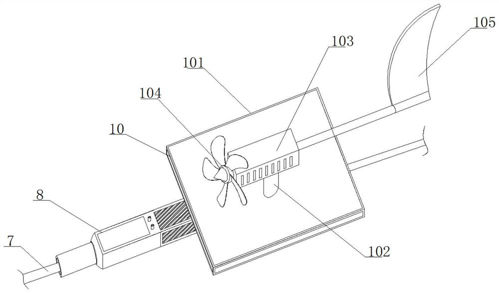
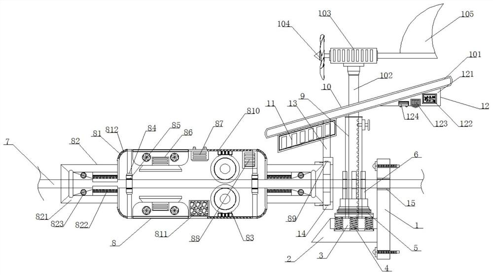
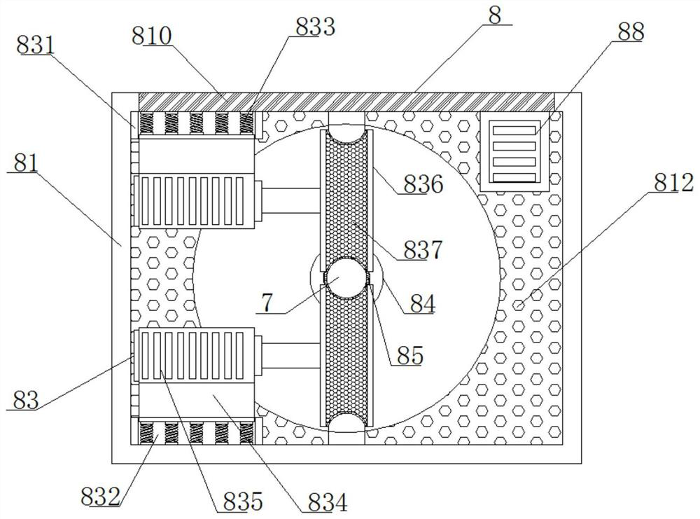
[0028] see Figure 1-5 , an automatic control, detection, protection and cleaning system for transmission lines, comprising a mounting plate 1, a horizontal plate 2 is fixedly installed at the left lower end of the mounting plate 1, a square groove 3 is opened on the top of the horizontal plate 2, and the square groove 3 Pressure springs 4 are fixedly installed at equal intervals inside, pressure sensors 5 are fixedly installed on the top of the pressure springs 4, three sets of detection rings 6 are fixedly installed at equal intervals on the top of the pressure sensors 5, and the inner sides of the three sets of detection rings 6 are slidingly connected There is a cable main body 7, the left side of the cable main body 7 is slidingly connected with a cleaning mechanism 8, the top of the horizontal plate 2 is fixedly installed with a telescopic rod 9 at the front end of the square groove 3, and the top of the telescopic rod 9 is fixedly installed with a An energy storage mech...


PUM


Abstract

A power transmission line automatic control detection protection cleaning system disclosed by the present invention comprises a mounting plate, a transverse plate is fixedly mounted at the lower end of the left side of the mounting plate, a square groove is formed in the top of the transverse plate, pressure springs are fixedly mounted in the square groove at equal intervals, and pressure sensors are fixedly mounted at the tops of the pressure springs. Three groups of detection rings are fixedly mounted at the top of the pressure sensor at equal intervals, a cable main body is slidably connected to the inner sides of the three groups of detection rings, and a cleaning mechanism is slidably connected to the left side of the cable main body; the system has enhanced cleaning capability, can perform intelligent detection, can clean the surface of a cable in rainy days, can well treat an ice layer on the surface when the cable is frozen, can effectively prolong the service life of a power transmission line, does not need an external circuit in the whole operation process, is relatively high in environmental protection property, can automatically store power, is self-sufficient, and is high in practicability, wide in application prospect and worthy of application and popularization.

Description

technical field [0001] The invention relates to the technical field of transmission line cleaning and protection, and more specifically relates to an automatic control, detection, protection and cleaning system for transmission lines. Background technique [0002] The transmission line is an important part used for power transmission from the power station to the user unit. Whether it is in the city or in the field, many transmission lines will be erected for power transmission; Such as bird droppings, balloon leads, kite wires, plastic bags, etc., and in some cold regions, the surface of the transmission line is more likely to freeze after rain and snow, thus increasing the burden on the transmission line. The rain and snow freezing disasters caused a large amount of ice on the surface of the transmission line, which led to the failure of the urban power system. It is considered that the cleaning is cumbersome and dangerous. Therefore, we propose an automatic control, detec...

Claims


Application Information

Patent Timeline
Patent Type & Authority Applications(China)
IPC IPC(8): H02G1/02H02G7/16G01D21/02H02J7/35H02S10/12
CPCH02G1/02H02G7/16G01D21/02H02J7/35H02S10/12Y02E10/50
Inventor 田彦彦吴晓蕊牛瑞利
Owner 许昌皓硕环保科技有限公司
Why Eureka
Try Eureka