
Adjustable insulation supporting device for side contact conductor rail

A technology of insulating support and conductive rails, applied in the direction of driving rail devices, power rails, power lines, etc., can solve the problems of adjustment methods and installation layouts that are difficult to meet, and achieve the effects of high cost performance, elimination of installation gaps, and convenient adjustment

Pending Publication Date: 2021-09-17
CHINA RAILWAY HIGH SPEED ELECTRIFICATION EQUIP CORP LTD
View PDF0 Cites 0 Cited by
  • Summary
  • Abstract
  • Description
  • Claims
  • Application Information

AI Technical Summary

Problems solved by technology

At present, in some newly developed maglev transportation systems, the power supply system is equipped with three conductive rails, of which two conductive rails need to be installed on the negative pole side of the track beam, and they are arranged on the same insulating support. It is difficult to meet the above requirements in the adjustment method and installation layout of the adjustable insulation bracket

Method used


Image

  • Adjustable insulation supporting device for side contact conductor rail
  • Adjustable insulation supporting device for side contact conductor rail
  • Adjustable insulation supporting device for side contact conductor rail

Examples


Embodiment 1

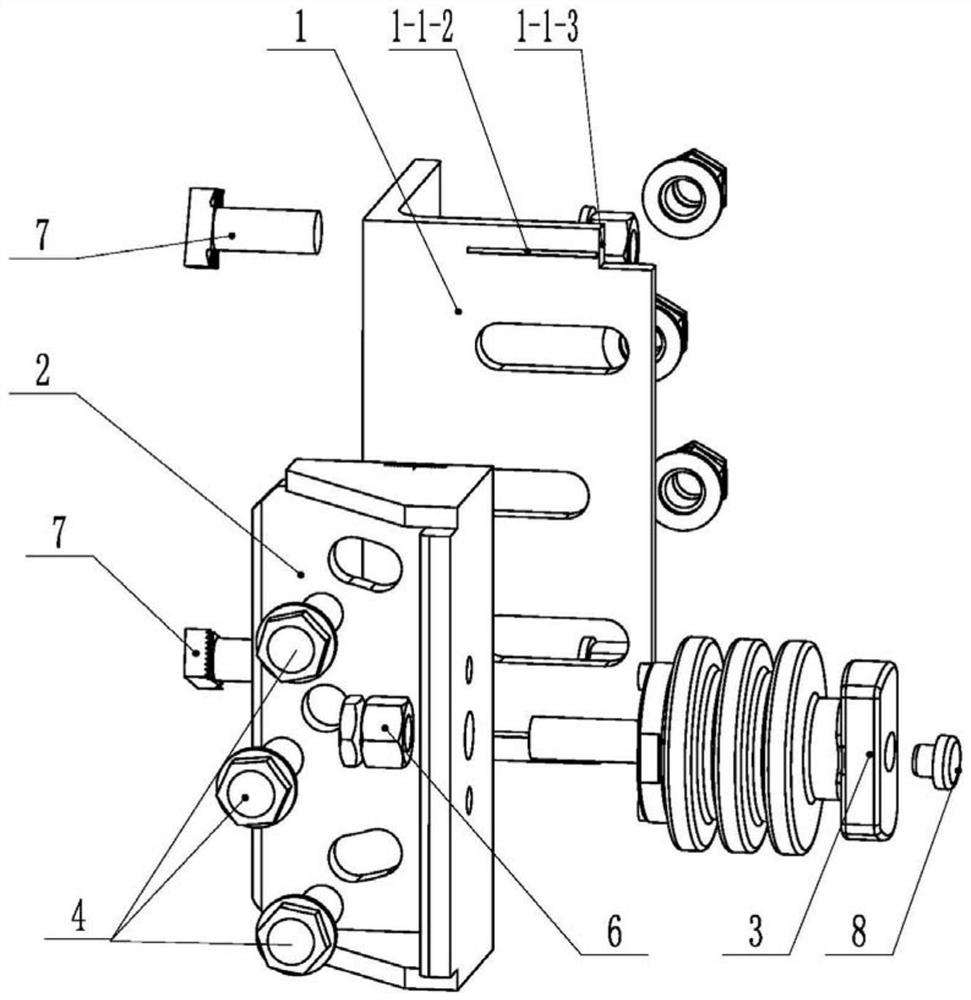
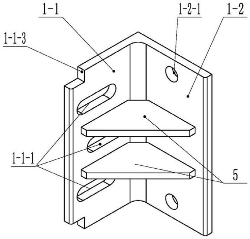
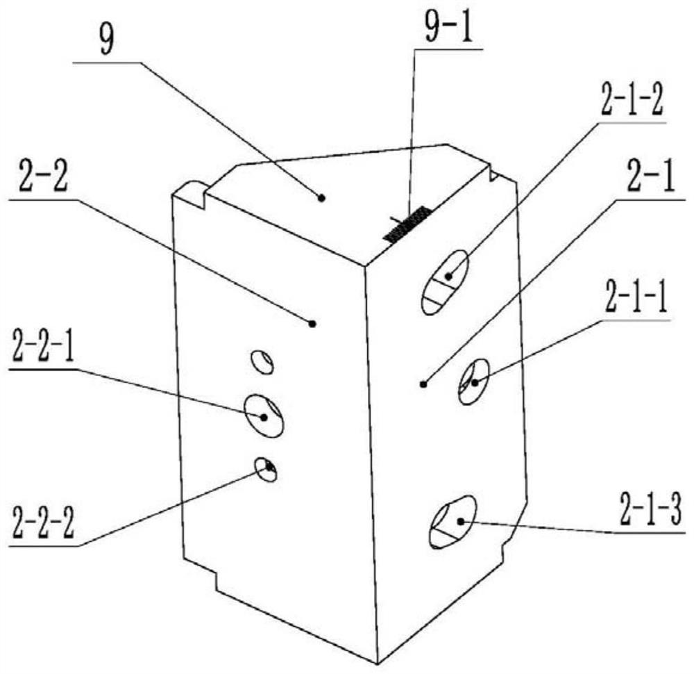
[0025] Embodiment 1: Installing a single side contact conductive rail adjustable insulating support device, including a support 1, a bracket 2, and an insulating support 3. The support 1 is composed of a first support plate 1-1 and a first installation plate 1- 2 form an L-shaped structure, and the upper, middle and lower positions of the first support plate 1-1 are respectively provided with horizontal strip holes 1-1-1; the bracket 2 is composed of the second support plate 2-2 and the second The mounting plate 2-1 forms an L-shaped structure, and the upper, middle, and lower positions of the second mounting plate 2-1 are respectively provided with a first circular arc long hole 2-1-2, a positioning hole 2-1-1 and a second Two circular arc long holes 2-1-3, and the first circular arc long hole 2-1-2 and the second circular arc long hole 2-1-3 are located at the circle centered on the center of the positioning hole 2-1-1 In the direction; the outer side of the second support p...

Embodiment 2

[0033] Embodiment 2: Install two side contact conductive rail adjustable insulating support devices, its basic structure is exactly the same as that of Embodiment 1, the difference is that the second support plate 2-2 has two upper and lower mounting holes 2- 2-1, and each mounting hole 2-2-1 has a positioning counterbore 2-2-2 above and below, and the inner end of the insulator 3-2 has two positioning posts 3-4, and the The position of the positioning column 3-4 corresponds to the positioning counterbore 2-2-2. Two insulating supports 3 are respectively installed and fixed on the two installation holes 2-2-1 according to the method described in Embodiment 1. When in use, the two conductive rails 11 are respectively clamped on the conductive rail block 3-1 at the outer end of the two insulating supports 3, the adjustment of the horizontal distance between the conductive rail 11 and the side of the track beam 10, and the adjustment of the inclination angle of the conductive rai...


PUM


Abstract

An adjustable insulation supporting device for a side contact conductor rail comprises a support, a bracket and an insulation support, and the support is provided with a horizontal strip-shaped hole; the bracket is provided with a first arc long hole, a positioning hole and a second arc long hole, and the first arc long hole and the second arc long hole are located in the circumferential direction with the center of the positioning hole as the circle center. An insulating support is horizontally fixed on the outer side of the bracket; the bracket penetrates through the first arc long hole, the positioning hole, the second arc long hole and the corresponding horizontal strip-shaped hole through a bolt pair to be connected to the outer side of the support, adjustment of the horizontal installation position of the bracket can be achieved through movement of the bolt pair along the horizontal strip-shaped hole, and vertical swing adjustment of the bracket can be achieved through rotation of the bracket around the positioning hole. Therefore, the adjustment of the horizontal position and the up-down swing position of the insulating support is realized. Adjustment of the installation position and the inclination angle of the conductor rail is achieved, installation and adjustment are convenient, the adjustment range is large, and civil engineering adaptability is high.

Description

technical field [0001] The invention belongs to the technical field of rail transit power supply, and in particular relates to an adjustable insulating support device for side contact conductive rails. Background technique [0002] Urban rail transit straddle monorail, air train and maglev lines all adopt the layout form of installing conductive rails on the side of the track beam to realize the contact between the conductive rail and the side of the locomotive collector shoe to take current. In order to ensure the quality of current intake, the installation of the conductive rail The position requirements are relatively high. Considering factors such as civil engineering errors and construction installation errors, the insulating support device that needs to be installed with conductive rails has the function of adjusting the installation position. At present, in some newly developed maglev transportation systems, the power supply system is equipped with three conductive ra...

Claims


Application Information

Patent Timeline
Patent Type & Authority Applications(China)
IPC IPC(8): B60M1/30B60M5/00F16F15/04
CPCB60M1/307B60M5/00F16F15/04
Inventor 卢涛林建刘娟赵金凤杨敏飞丁俊勇杜宝峰
Owner CHINA RAILWAY HIGH SPEED ELECTRIFICATION EQUIP CORP LTD
Learn More