Feeding device for wood board processing

A technology for wood boards and bottom boards, which is applied in the field of feeding devices for wood board processing, which can solve the problems of uneven regularity and low placement accuracy, and achieve better paths, accurate feeding positions, regular and high-efficiency feeding

Inactive Publication Date: 2021-09-17
和县薛氏木制品制造有限公司
0 Cites 1 Cited by

AI-Extracted Technical Summary

Problems solved by technology

[0004] The object of the present invention is to provide a feeding device for wood board processing to solve ...

Method used

In the present invention, push box 5 and the setting of conflicting wheel 12, carry plate 4 is lifted up together with sheet material by adjustment mechanism, after upper side plate material and conflicting wheel 12 lower ends mutually conflict, promptly finish the lifting of plate material At this time, the upper plate can be pushed out of the support plate 2 through the discharg...

Abstract

The invention discloses a feeding device for wood board processing. The feeding device comprises a bottom plate. A vertically-arranged supporting plate is fixedly connected to the upper end of the bottom plate, an adjusting box is fixedly connected to the upper end of the bottom plate, and a horizontally-arranged bearing plate is arranged on the upper side of the adjusting box and is slidably connected to the side wall of the supporting plate. An adjusting mechanism used for adjusting the position of the bearing plate is arranged in the adjusting box, a pushing box is fixedly connected to the upper end of the supporting plate, the pushing box is provided with a pushing mechanism used for pushing boards, and a maintaining mechanism used for keeping the positions of the boards accurate is arranged on the side, away from the bearing plate, of the supporting plate. Through the arrangement of the pushing box, the board pushing action is smoother, and meanwhile the path is better; and through the arrangement of sliding frames, the feeding position of each board can be kept accurate.

Application Domain

ConveyorsDe-stacking articles +1

Technology Topic

EngineeringStructural engineering +3

Image

  • Feeding device for wood board processing
  • Feeding device for wood board processing
  • Feeding device for wood board processing

Examples

  • Experimental program(1)

Example Embodiment

[0021] The following will clearly and completely describe the technical solutions in the embodiments of the present invention with reference to the accompanying drawings in the embodiments of the present invention. Obviously, the described embodiments are only some, not all, embodiments of the present invention. Based on the embodiments of the present invention, all other embodiments obtained by persons of ordinary skill in the art without making creative efforts belong to the protection scope of the present invention.
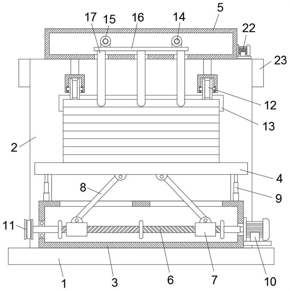
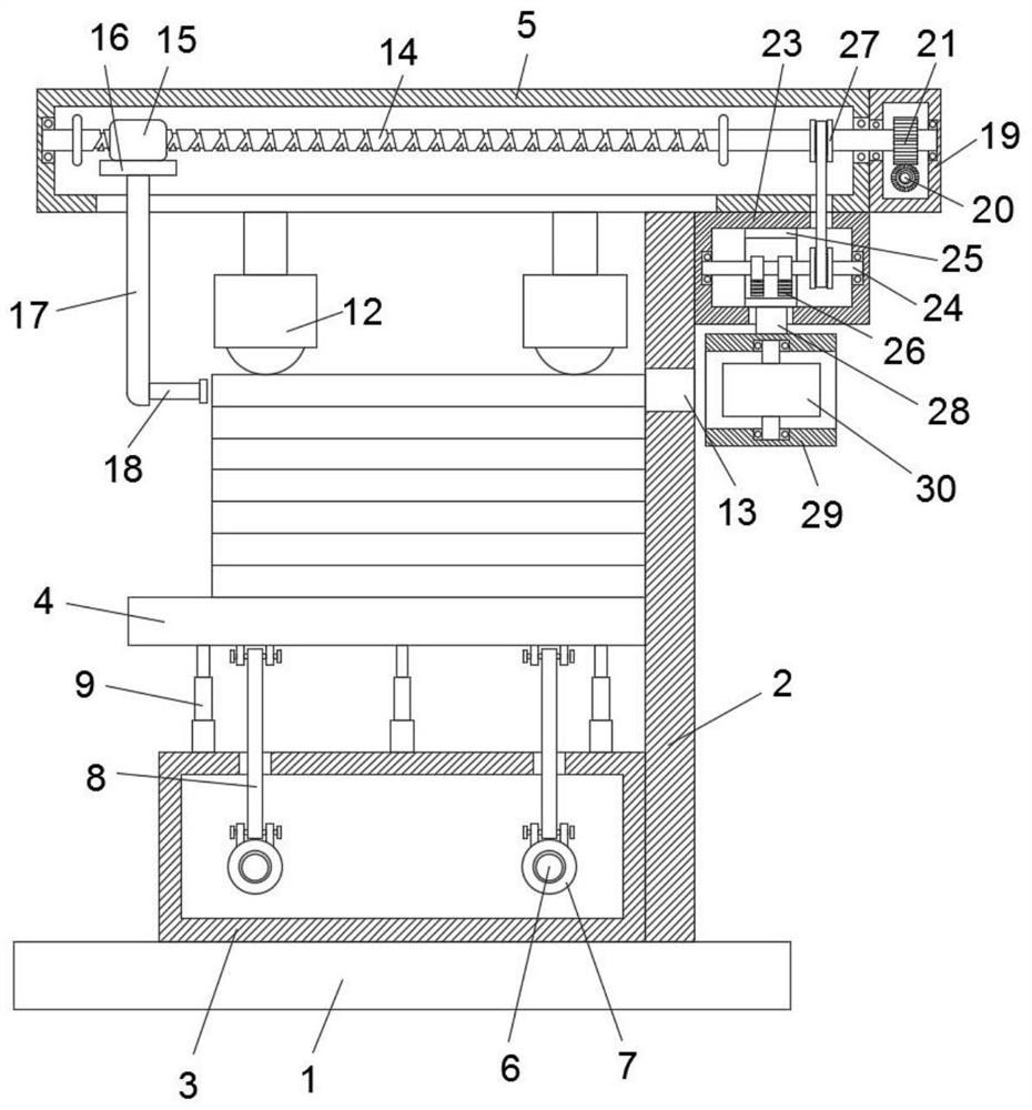
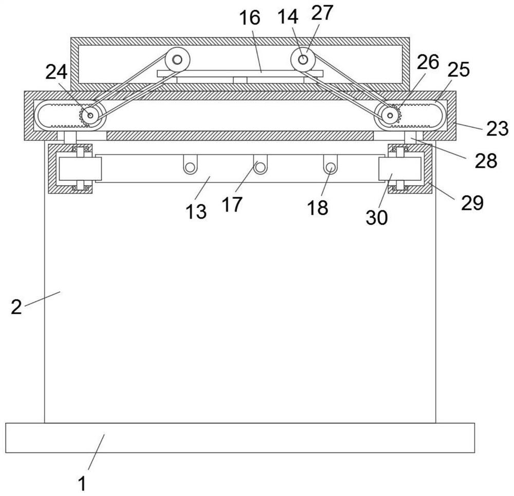
[0022] see Figure 1-3 , an embodiment provided by the present invention:
[0023] A feeding device for wood board processing, comprising a bottom plate 1, the upper end of the bottom plate 1 is fixedly connected with a support plate 2 with numerical setting, the upper end of the bottom plate 1 is fixedly connected with an adjustment box 3, and the upper side of the adjustment box 3 is provided with a horizontally arranged bearing plate 4, The bearing plate 4 is slidably connected to the side wall of the support plate 2. It is worth mentioning that the lower end of the push box 5 is fixedly connected with a plurality of conflicting wheels 12, and the position corresponding to the lower side of the conflicting wheels 12 on the support plate 2 is provided with a discharge wheel. port 13, the adjustment box 3 is provided with an adjustment mechanism for adjusting the position of the bearing plate 4.
[0024] In the present invention, the adjustment mechanism includes two threaded rods 6 arranged horizontally, and the two threaded rods 6 are all rotatably connected to the inner wall of the adjustment box 3. A threaded sleeve 7 is evenly sleeved, and the upper end of the threaded sleeve 7 is rotatably connected with an adjustment rod 8 , and the upper end of the adjustment rod 8 slides through the upper side wall of the adjustment box 3 and is rotatably connected to the lower end of the bearing plate 4 .
[0025] In the present invention, the bearing plate 4 is fixedly connected to the upper end of the adjustment box 3 through a plurality of telescopic rods 9, and the outer wall of the adjustment box 3 is fixedly equipped with a first motor 10, and the output end of the first motor 10 rotates through the side wall of the adjustment box 3 and is connected with it. One threaded rod 6 is coaxially fixedly connected, and the ends of the two threaded rods 6 away from the first motor 10 both rotate through the side wall of the adjustment box 3 and are fixedly sleeved with a transmission disc 11, and the two transmission discs 11 are mutually driven by the same belt .
[0026] In the present invention, the push box 5 is fixedly connected to the upper end of the support plate 2, and the push box 5 is provided with a push mechanism for pushing the plate. The inner wall of the push box 5, and the two reciprocating screw rods 14 are equipped with reciprocating sleeves 15, the lower ends of the two reciprocating sleeves 15 are fixedly connected with the same sliding plate 16, and the lower ends of the sliding plate 16 are fixedly connected with multiple push rods 17. The lower ends of the plurality of push rods 17 slide through the lower side wall of the push box 5 and extend to the lower side of the push box 5, and the side walls of the plurality of push rods 17 close to the support plate 2 are fixedly connected with extension push rods 18.
[0027] In the present invention, the outer wall of the push box 5 is fixedly connected with the drive box 19, and the ends of the two reciprocating screw rods 14 near the drive box all rotate through the side wall of the push box 5 and are rotatably connected to the inner side wall of the drive box 19. There is a horizontally arranged worm 20, and the positions corresponding to the worm 20 on the two reciprocating screw rods 14 are fixedly sleeved with a worm wheel 21, and the worm 20 and the worm wheel 21 mesh with each other.
[0028] In the present invention, a second motor 22 is fixedly installed on the outer wall of the drive box 19, the output end of the second motor 22 rotates through the side wall of the drive box 19 and is coaxially fixedly connected with one end of the worm 20, and the other end of the worm 20 is rotatably connected to the drive box 19 inner wall.
[0029] In the present invention, the setting of the push box 5 and the conflicting wheel 12 lifts the carrying plate 4 together with the plate through the adjustment mechanism. When the upper plate and the lower end of the conflicting wheel 12 collide with each other, the lifting of the plate is completed. That is, through the reciprocating sleeve 15 and a plurality of push rods 17, the upper side plate can be pushed out of the support plate 2 through the discharge port 13, and the repeated work of the adjustment mechanism and the push mechanism can make the feeding of the plate more regular and efficient. The presence of the upper side of the friction wheel 12 makes the movement of the plate more smooth and the path better when it is pushed
[0030] In the present invention, the side of the support plate 2 away from the bearing plate 4 is provided with a maintenance mechanism for maintaining the accurate position of the plate. The maintenance mechanism includes a maintenance box 23. Sliding frames 25 are all set, and the inner wall of the sliding frame 25 is provided with ruler teeth and is slidably connected to the inner wall of the maintenance box 23, and the half gear 26 is fixedly sleeved on the rotating shaft 24, and the ruler teeth of the half gear 26 and the inner wall of the sliding frame 25 Mesh with each other, and the two rotating shafts 24 and the reciprocating screw mandrel 14 are fixedly sleeved with drive discs 27, and the two drive discs 27 that are close to each other are mutually driven by the same belt.
[0031]In the present invention, the lower ends of the two sliding frames 25 are fixedly connected with connecting blocks 28, and the lower ends of the connecting blocks 28 slide through the lower side walls of the maintenance box 23 and are fixedly connected with the stabilizing boxes 29, and the opposite side walls of the stabilizing boxes 29 on both sides are penetrated Openings are provided, and guide wheels 30 are rotatably connected to the inner walls of the two stability boxes 29 .
[0032] In the present invention, the setting of the sliding frame 25 and the stabilizing box 29, when the internal mechanism of the drive box 19 drives the two reciprocating screw mandrels 14 to rotate, the rotating shaft 24 can follow the reciprocating screw mandrels 14 to rotate at the same time, and then through the half gear on the rotating shaft 24 26 engages the chi teeth on the inner side wall of the sliding frame 25, and then the connecting rods at the lower end of the sliding frame 25 drive the stabilizing boxes 29 on both sides to approach each other, so that the position of the plate passing through the discharge port 13 can be limited, so that the plate is held by the two sides. The stabilizing box 29 and the guide wheel 30 are pressed against the middle position, and the teeth of the inner wall of the ring frame are repeatedly meshed by the half gear 26, so as to cooperate with the movement of each plate and maintain the position of each plate, so that each plate The feeding position of each board is kept accurate.
[0033] Working principle: After placing the plate on the carrier plate 4, start the output end of the first motor 10 to rotate forward, at this time, the output end of the first motor 10 drives the threaded rod 6 to rotate, and the two threaded rods 6 rotate simultaneously through the transmission of the transmission disc 11 And drive the threaded sleeve 7 to move towards each other, and then push the carrier plate 4 upwards through the adjustment rod 8 until the upper side plate moves to the lower end of the conflicting wheel 12 and then the first motor 10 can be turned off. When the second motor 22 can be turned on, the output end of the second motor 22 drives the worm screw 20 to rotate, and the rotation of the worm screw 20 is transmitted to the two reciprocating screw mandrels 14 through the worm wheel 21. At this time, the two reciprocating screw mandrels 14 rotate simultaneously and drive two A reciprocating sleeve 15 drives the sliding plate 16 and the push rod 17 to push the plate, and the extension push rod 18 at the lower end of the push rod 17 pushes the plate toward the discharge port 13, while the reciprocating screw rod 14 drives two through the driving disc 27. Rotating shaft 24 rotates, and rotating shaft 24 rotates and drives semi-gear 26 to engage the chi teeth of sliding frame 25 inner side walls, earlier makes two sliding frames 25 approach each other, and the connecting piece 28 of sliding frame 25 lower ends drives stabilizing box 29 to approach mutually, can pass stabilizing The guide wheel 30 inside the box 29 limits the position and navigates the direction of the plate, so that the plate can be in an accurate loading position after passing through the discharge port 13. After a plate is loaded, the output end of the first motor 10 starts again and Move the board up again and reciprocate to complete the regular and efficient feeding of the board.
[0034] It will be apparent to those skilled in the art that the invention is not limited to the details of the above-described exemplary embodiments, but that the invention can be embodied in other specific forms without departing from the spirit or essential characteristics of the invention. Accordingly, the embodiments should be regarded in all points of view as exemplary and not restrictive, the scope of the invention being defined by the appended claims rather than the foregoing description, and it is therefore intended that the scope of the invention be defined by the appended claims rather than by the foregoing description. All changes within the meaning and range of equivalents of the elements are embraced in the present invention. Any reference sign in a claim should not be construed as limiting the claim concerned.

PUM

no PUM

Description & Claims & Application Information

We can also present the details of the Description, Claims and Application information to help users get a comprehensive understanding of the technical details of the patent, such as background art, summary of invention, brief description of drawings, description of embodiments, and other original content. On the other hand, users can also determine the specific scope of protection of the technology through the list of claims; as well as understand the changes in the life cycle of the technology with the presentation of the patent timeline. Login to view more.

Similar technology patents

Automatic intelligent sorting file cabinet

InactiveCN1981669Areduce movementsmooth motion
Owner:蔡建平

Carton output paper pushing device for carton pasting machine

InactiveCN106965492Asmooth motionaccelerate
Owner:天津连升包装制品有限公司

Classification and recommendation of technical efficacy words

  • smooth motion

Press machine

ActiveCN104669657Asmooth motionavoid damage
Owner:NINGBO LONGTIME MACHINE

Floating frame driving type flip-flop screen

InactiveCN105195412ASimple structuresmooth motion
Owner:CHINA UNIV OF MINING & TECH (BEIJING)

Display device

InactiveCN107481621ASimple structuresmooth motion
Owner:TCL CHINA STAR OPTOELECTRONICS TECH CO LTD
Why Eureka
Try Eureka