Pixel driving circuit, display panel, control method of display panel and display equipment

A pixel drive circuit and display panel technology, applied to static indicators, instruments, etc., can solve the problems of reducing the display effect of electronic equipment, RC load, and uneven display brightness, so as to shorten the charging time of the anode, ensure uniformity, and improve Show the effect of the effect

Active Publication Date: 2021-09-17
GUANGDONG OPPO MOBILE TELECOMM CORP LTD
View PDF5 Cites 3 Cited by
  • Summary
  • Abstract
  • Description
  • Claims
  • Application Information

AI Technical Summary

Problems solved by technology

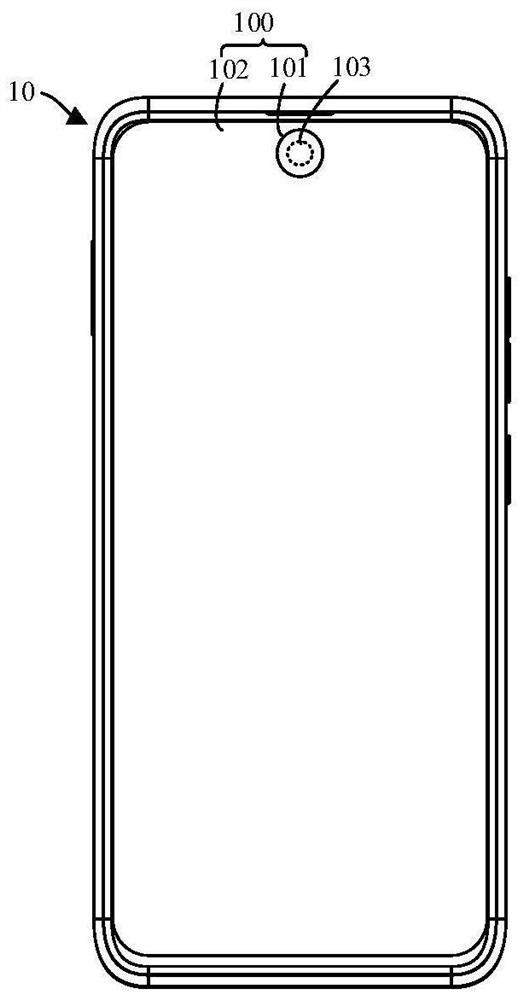
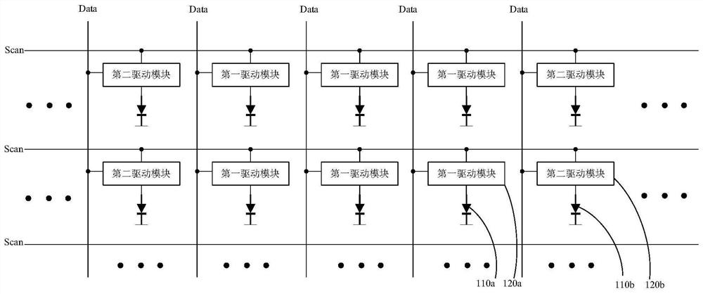
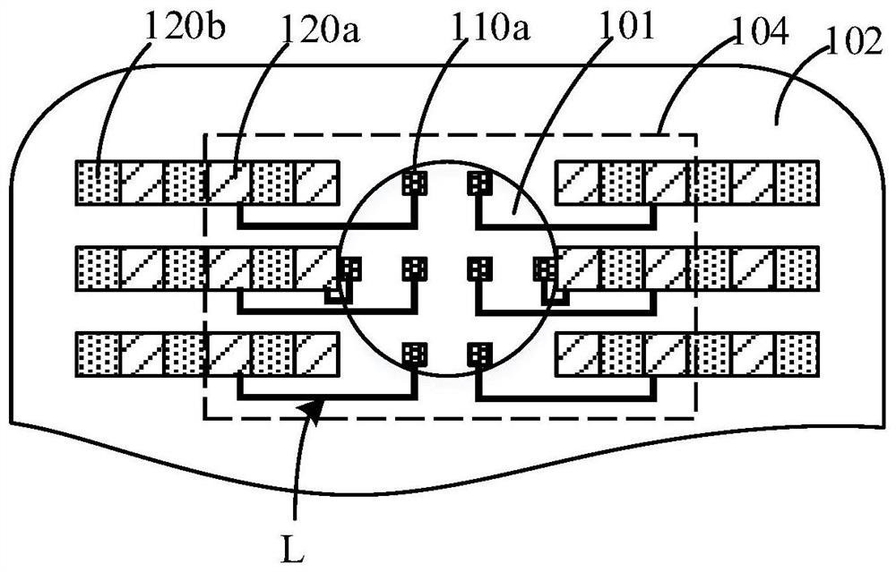
Since the light-emitting device of the second display area is usually arranged in the visual area of ​​the camera (for example, the second display area), and the pixel circuit of the light-emitting device is arranged on the periphery of the second display area, the light-emitting device and the pixel circuit are connected by metal wires. Wire connection, it is easy to generate RC load on the metal wire, so that when the light-emitting device in the first display area and the light-emitting device in the second display area are driven at the same time, the display brightness of the first display area and the second display area are not uniform, reducing The display effect of electronic equipment

Method used


Image

  • Pixel driving circuit, display panel, control method of display panel and display equipment
  • Pixel driving circuit, display panel, control method of display panel and display equipment
  • Pixel driving circuit, display panel, control method of display panel and display equipment

Examples


Embodiment Construction

[0032] In order to facilitate understanding of the embodiments of the present application, the following will describe the embodiments of the present application more comprehensively with reference to related drawings. A preferred embodiment of the embodiments of the application is given in the accompanying drawings. However, the embodiments of the present application can be implemented in many different forms, and are not limited to the embodiments described herein. On the contrary, the purpose of providing these embodiments is to make the disclosure of the embodiments of the present application more thorough and comprehensive.

[0033] Unless otherwise defined, all technical and scientific terms used herein have the same meaning as commonly understood by one of ordinary skill in the technical field of the embodiments of this application. The terms used herein in the description of the embodiments of the present application are only for the purpose of describing specific emb...


PUM


Abstract

An embodiment of the invention relates to a pixel driving circuit, a display panel, a control method of the display panel and display equipment. The pixel driving circuit comprises a plurality of driving modules, wherein each driving module is used for driving a light emitting device connected with the driving module; each driving module comprises an anode reset unit, a driving transistor, and a target metal wire used for connecting the anode reset unit and light-emitting devices; the control end of each anode reset unit is used for receiving a first scanning signal, the input end of the anode reset unit is used for receiving a first reset voltage, and the output end of the anode reset unit is respectively connected with a first electrode of the corresponding driving transistor and an anode of the corresponding light-emitting device; and the first reset voltage received by the input end of each anode reset unit is positively correlated with the length of the corresponding target metal wire. Therefore, the influence of RC load generated by the metal wire on the lighting time of each light-emitting device can be reduced, the brightness uniformity of the light-emitting devices in the first display area is ensured, and the display effect is ensured to be improved.

Description

technical field [0001] The embodiments of the present application relate to the field of display technology, and in particular, to a pixel driving circuit, a display panel, a control method thereof, and a display device. Background technique [0002] With the continuous development of science and technology, electronic equipment emerges in an endless stream, which brings great convenience to people's daily life and entertainment. At present, electronic devices are constantly developing towards larger screens. In order to increase the screen-to-body ratio of electronic devices and truly realize a full screen, under-screen camera technology has attracted much attention. [0003] Due to the existence of the under-screen camera, the under-screen camera can divide the display screen of the electronic device into a first display area (main screen area) and a second display area (secondary screen area), that is, the area where the under-screen camera is placed. Since the light-emi...

Claims


Application Information

Patent Timeline
Patent Type & Authority Applications(China)
IPC IPC(8): G09G3/3208G09G3/32
CPCG09G3/3208G09G3/32
Inventor 刘长瑜
Owner GUANGDONG OPPO MOBILE TELECOMM CORP LTD
Why Eureka
Try Eureka