Quick and batch clamping jig for linear cutting machining

A wire cutting and jig technology, which is used in the field of fast and batch clamping fixtures, can solve the problems of inability to guarantee the centring error, wasting time, and cumbersome processes, so as to reduce the time for calibration and centring, with good effects and lightening The effect of workload

Active Publication Date: 2021-09-21
深圳市三精模具有限公司
View PDF12 Cites 0 Cited by
  • Summary
  • Abstract
  • Description
  • Claims
  • Application Information

AI Technical Summary

Problems solved by technology

This processing method can only fix one entry at a time, and there is no zero reference position when the entry is divided into numbers. Every time an entry is processed, it must be divided and counted several times. The process is cumbersome and very time-consuming (one It takes about 15 minutes for the average time to correct the centering of the inserts), and there is no guarantee that there will be no centering errors when each insert is cut online. If there is an error, the processed inserts will be scrapped

Method used


Image

  • Quick and batch clamping jig for linear cutting machining

Examples


Embodiment Construction

[0017] The invention proposes a fast and batch clamping jig for wire cutting.

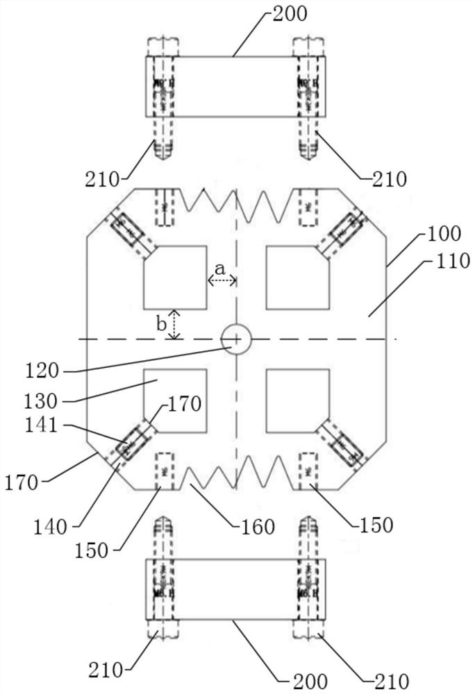
[0018] refer to figure 1 , figure 1 It is a schematic diagram of dismantling the top view structure of an embodiment of the present invention.

[0019] Such as figure 1 As shown, in the embodiment of the present invention, the fast and batch clamping jig for wire cutting includes: a jig body 100 with a square clamping surface 110 and an auxiliary fixture body 100 detachably connected 200 pieces.

[0020] The center of the clamping surface 110 is provided with a center zero hole 120, and the inner sides of the four right-angled sides of the clamping surface 110 are provided with square holes 130 for placing square inserts. The centers of the zero hole 120 coincide, and the surrounding sidewalls of the square hole 130 are parallel to the surrounding sidewalls of the jig body 100 . The side length of the square hole 130 is not less than 20mm, and a square insert with a side length≤20×20mm can be ...


PUM

PropertyMeasurementUnit
lengthaaaaaaaaaa

Abstract

The invention discloses a quick and batch clamping jig for linear cutting machining. The quick and batch clamping jig comprises a jig body and auxiliary parts. The jig body is provided with a centering zero position hole and four square holes, and the geometric centers of the four square holes coincide with the center of the centering zero position hole. Threaded through holes communicating with the square holes in a one-to-one correspondence manner are formed in the side wall of the jig body, and grub screws are connected into the threaded through holes in a threaded manner. Two threaded blind holes and a plurality of V-shaped grooves used for containing cylindrical inserts are symmetrically formed in a set of opposite side walls of the jig body, and the cylindrical inserts placed in the V-shaped grooves are tightly abutted through the auxiliary parts. The quick and batch clamping jig has the beneficial effects that the jig not only can clamp and fix the inserts, but also can correct the reference surface and conduct centering, so that the correcting and centering time before linear cutting is greatly shortened. The correcting and centering effects are good, and the machining precision of the mold inserts is guaranteed. The plurality of mold inserts can be machined at a time, so that the machining efficiency is greatly improved.

Description

technical field [0001] The invention relates to the technical field of wire-cut processing mold inserts, in particular to a fast and batch clamping jig for wire-cut processing. Background technique [0002] Wire cutting is a very important process in the processing of mold inserts. When processing inserts by wire cutting, it is necessary to divide the inserts first. The centering of wire cutting refers to finding the center point of the part. Take a square part as an example. When centering, adjust the spark, let the spark touch one side, and reset the scale of the hand wheel to zero, then let the spark touch the opposite side, and see the number of scales. , the number of scales divided by two is the center position of the two opposite sides, and the other two opposite sides are also operated in the same way. [0003] At present, when wire cutting inserts are processed, the inserts are directly fixed on the working platform, and the working platform is used as the referenc...

Claims


Application Information

Patent Timeline
Patent Type & Authority Applications(China)
IPC IPC(8): B23H7/02B23H11/00
CPCB23H11/00B23H7/02
Inventor 何海鸥黄翔球
Owner 深圳市三精模具有限公司
Why Eureka
Try Eureka