Method and device for determining actual position of object in fisheye camera image

A technology of fisheye camera and actual position, which is applied in the field of image processing, can solve the problems of inaccurate positioning and affecting the accuracy of imaging position, and achieve the effect of simple and efficient method

Active Publication Date: 2021-09-21
上海迈外迪网络科技有限公司
View PDF10 Cites 1 Cited by
  • Summary
  • Abstract
  • Description
  • Claims
  • Application Information

AI Technical Summary

Problems solved by technology

[0006] Barrel distortion will affect the position accuracy of imaging. In the monitoring system based on fisheye camera and deep learning, the barrel distortion of fisheye camera (and camera installation error) will cause the position of the object in the image in the real world coordinate system The positioning is not accurate

Method used


Image

  • Method and device for determining actual position of object in fisheye camera image
  • Method and device for determining actual position of object in fisheye camera image
  • Method and device for determining actual position of object in fisheye camera image

Examples


Embodiment 1

[0059] As described below, an embodiment of the present invention provides a method for determining the actual position of an object in a fisheye camera image.

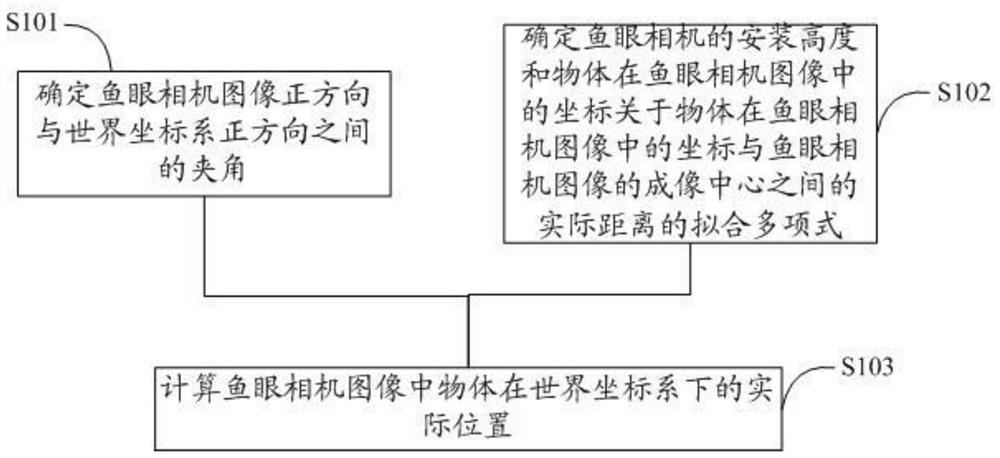
[0060] refer to figure 1 The flow chart of the method for determining the actual position of an object in a fisheye camera image is shown in detail below through specific steps:

[0061] S101. Determine the included angle between the positive direction of the fisheye camera image and the positive direction of the world coordinate system.

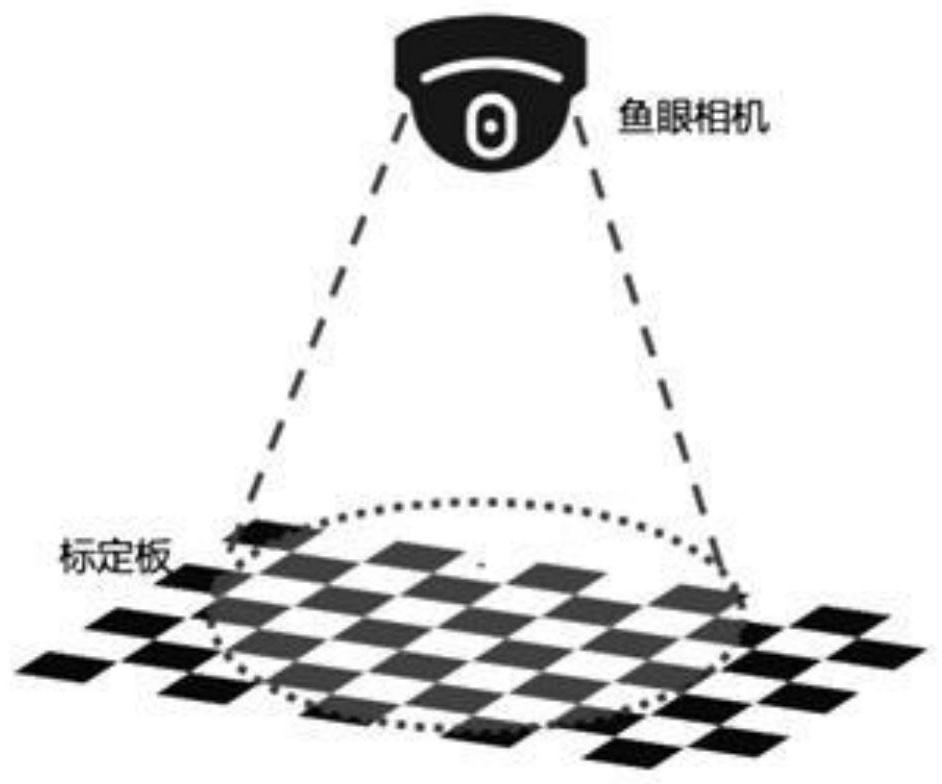
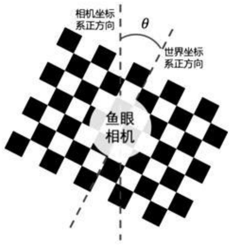
[0062] Such as figure 2 , image 3 As shown, in some embodiments, said determining the angle (θ) between the positive direction of the fisheye camera image and the positive direction of the world coordinate system includes:

[0063] Place the calibration board under the fisheye camera lens, and calculate the position of each corner point on the calibration board;

[0064] The angle between the positive direction of the fisheye camera image coordinate system and the positive dir...

Embodiment 2

[0089] As described below, an embodiment of the present invention provides a device for determining the actual position of an object in a fisheye camera image, including:

[0090] a processor adapted to load and execute instructions of a software program;

[0091] A memory adapted to store a software program comprising instructions for performing the following steps:

[0092] Determine the angle θ between the positive direction of the fisheye camera image and the positive direction of the world coordinate system; specifically, include:

[0093] Place the calibration board under the fisheye camera lens, and calculate the position of each corner point on the calibration board;

[0094] The angle between the positive direction of the fisheye camera image coordinate system and the positive direction of the world coordinate system where the calibration plate is located is used as the angle θ between the positive direction of the fisheye camera image and the positive direction of the...


PUM


Abstract

The invention discloses a method and device for determining the actual position of an object in a fisheye camera image. The method comprises the following steps: determining an included angle between the positive direction of the fisheye camera image and the positive direction of a world coordinate system; determining a fitting polynomial of the installation height of the fisheye camera and the coordinate of the object in the fisheye camera image with respect to the actual distance between the coordinate of the object in the fisheye camera image and the imaging center of the fisheye camera image; and calculating the actual position of the object in the fisheye camera image under the world coordinate system. According to the invention, the actual position of the object in the image in the real world coordinate system is efficiently and accurately estimated. The mounting plane of the fisheye camera is parallel to the ground below the mounting position of the fisheye camera; meanwhile, the included angle between the positive direction of the image of the fisheye camera and the positive direction of the world coordinate system and the installation height of the fisheye camera are determined by means of the calibration plate. The efficiency is high.

Description

technical field [0001] The invention relates to the technical field of image processing, in particular to a method and a device for determining the actual position of an object in a fisheye camera image. Background technique [0002] Fisheye lens refers to a lens with a focal length of 16nm or less and a viewing angle close to or equal to 180°. It is an extreme wide-angle lens. In order to achieve the maximum viewing angle of the lens, the diameter of the front lens of the fisheye lens is very short and protrudes toward the front of the lens in a parabola shape, which is similar to the eyes of a fish, hence the name. [0003] A fisheye camera is a camera with a fisheye lens. As mentioned earlier, it has an extremely short focal length (16nm or less) and a viewing angle close to or equal to 180° [0004] It is understandable that the extremely short focal length, while bringing a larger viewing angle range, will also produce certain disadvantages, such as barrel distortion....

Claims


Application Information

Patent Timeline
Patent Type & Authority Applications(China)
IPC IPC(8): G06T7/70G06T7/80G06T3/00
CPCG06T7/70G06T7/80G06T3/0018Y02A40/81
Inventor 杨录辛学仕姚生意张程
Owner 上海迈外迪网络科技有限公司
Why Eureka
Try Eureka