

Construction method for manufacturing reinforcement cage by seam welder for highway engineering
A technology of rolling welding machine and steel cage, which is applied in the field of road and bridge engineering, can solve problems such as poor stability, and achieve the effects of improving stability, ensuring service strength, and improving engineering quality
- Summary
- Abstract
- Description
- Claims
- Application Information
AI Technical Summary
Problems solved by technology
Method used
Image

Examples
Embodiment Construction
[0054] The technical solutions in the present invention will be further described below in conjunction with the accompanying drawings and embodiments.
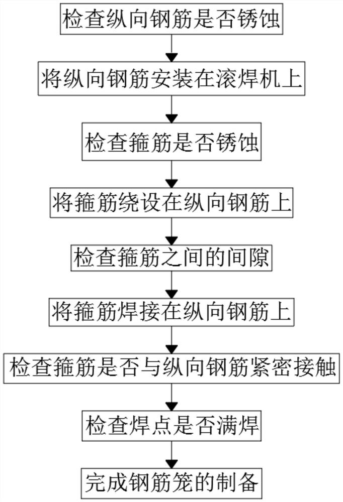
[0055] Such as figure 1 Shown, for the embodiment of the present invention proposes the seam welding machine that is used for highway engineering to make steel cage construction method, comprises the steps:
[0056] S1: Before installing the longitudinal reinforcement 6, check whether the longitudinal reinforcement 6 is corroded, and obtain uncorroded longitudinal reinforcement 6;
[0057] S2: install the non-corroded longitudinal reinforcement 6 on the seam welding machine;
[0058] S3: Before connecting the stirrup 5 to the feeding mechanism of the seam welding machine, check whether the stirrup 5 is corroded, and obtain an uncorroded stirrup 5;
[0059] S4: connecting the non-corroded stirrup 5 to the feeding mechanism of the seam welding machine, so that the seam welding machine winds the stirrup 5 on the longitudinal st...
PUM
 Abstract
Description
Claims
Application Information