High-efficiency resonator manufacturing device

A technology for manufacturing devices and resonators, which is applied in the field of high-efficiency resonator manufacturing devices, can solve the problems of high production costs and heavy labor, and achieve the effect of reducing labor costs and improving production efficiency

Active Publication Date: 2021-09-24
金华市创捷电子有限公司
View PDF8 Cites 0 Cited by
  • Summary
  • Abstract
  • Description
  • Claims
  • Application Information

AI Technical Summary

Problems solved by technology

[0002] The resonator is mainly composed of the following parts: input, output electrodes, bias voltage electrodes, vibration plate, anchor structure, substrate and control circuit, and the input and output electrodes are generally welded with pins, and the current welding has manual welding Completed, and from the pin welding to the dot machine, it needs to go through a series of cumbersome processes of blanking, transportation, clamping, and welding, and it needs to be transferred and transported many times in the whole process, which creates a lot of labor and needs to be used A large number of personnel, the production cost has been high

Method used


Image

  • High-efficiency resonator manufacturing device
  • High-efficiency resonator manufacturing device
  • High-efficiency resonator manufacturing device

Examples


Embodiment 1

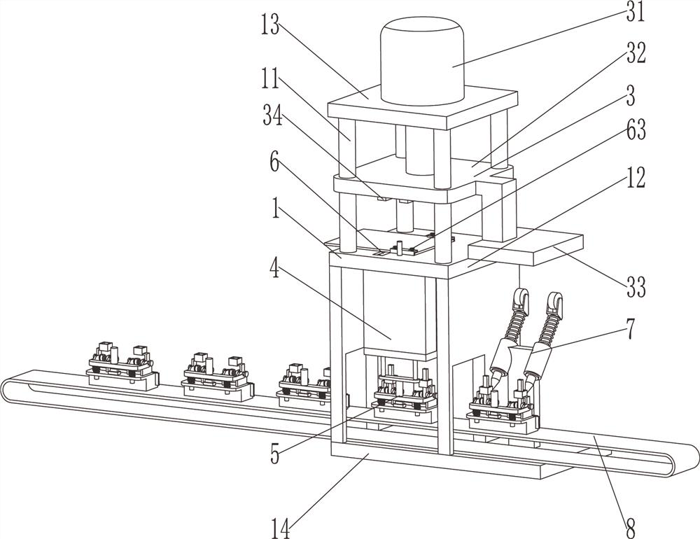
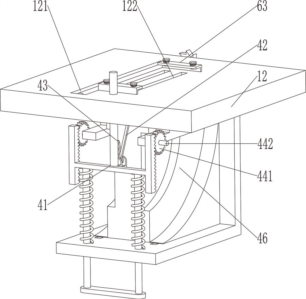
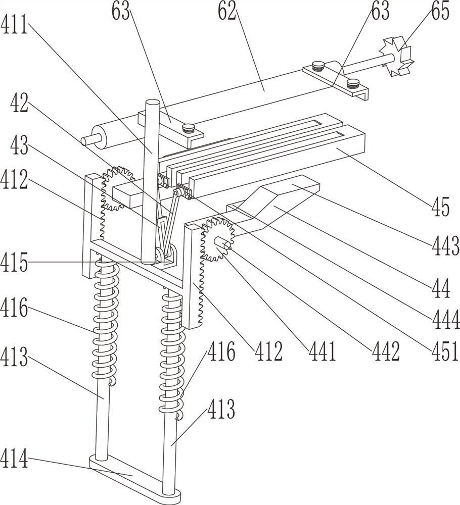
[0025] see Figure 1-Figure 5 , a high-efficiency resonator manufacturing device, including a base 1, a stamping part 3 and a distribution mechanism 4, the base 1 includes a cavity plate 12, an upper top plate 13 and a lower bottom surface 14, the cavity plate 12 and the upper top plate 13 Several guide rods 11 are provided, and the stamping part 3 includes a stamping power part 31, a stamping sliding plate 32, a shifting tooth combination 35 and a linkage plate 33, and the stamping sliding plate 32 is slidably arranged on the guide rod 11, and the stamping power The component 31 is arranged on the top of the base 1, and its telescoping rod is connected with the stamping sliding plate 32, wherein it provides the power to slide up and down for the stamping sliding plate 32, the bottom of the stamping sliding plate 32 is provided with a punch 34, the cavity plate 12 A punching hole 122 is arranged on the top, and such a resonator is a double-pin design, so there are two punches ...

Embodiment 2

[0032] see Figure 1-Figure 9, a high-efficiency resonator manufacturing device, including a base 1, a stamping part 3, a welding mechanism 7, a feeding mechanism 6, a distribution mechanism 4, a conveying mechanism 5 and a clamping device 5, the base 1 includes a cavity plate 12, an upper The top plate 13 and the lower bottom surface 14, the cavity plate 12 and the upper top plate 13 are provided with several guide rods 11, and the stamping part 3 includes a stamping power part 31, a stamping sliding plate 32, a shifting tooth combination 35 and a linkage plate 33. The stamping sliding plate 32 is slidingly arranged on the guide rod 11, the stamping power part 31 is arranged on the top of the base 1, and its telescopic rod is connected with the stamping sliding plate 32, wherein it provides the power for the stamping sliding plate 32 to slide up and down, A punch 34 is provided at the bottom of the stamping sliding plate 32, and a punching hole 122 is arranged on the cavity p...


PUM


Abstract

The invention discloses a high-efficiency resonator manufacturing device which comprises a base and a stamping part. The stamping part is arranged on the base and used for stamping a plate to form pins of a resonator; a sub-conveying mechanism used for moving and overturning the pins subjected to stamping is arranged below the base; and the stamping part slides up and down to drive the sub-conveying mechanism to operate. According to the high-efficiency resonator manufacturing device provided by the invention, automatic collecting and automatic separating overturning of the pins after stamping is completed are achieved, preparation is made for the next automatic clamping procedure, automation is achieved by collecting materials after stamping and automatically overturning the pins to enter the next procedure for work, the probability of errors caused by human factors is effectively eradicated, the production efficiency is improved, and the labor cost is reduced.

Description

technical field [0001] The invention relates to the technical field of resonator manufacturing equipment, in particular to a high-efficiency resonator manufacturing device. Background technique [0002] The resonator is mainly composed of the following parts: input, output electrodes, bias voltage electrodes, vibration plate, anchor structure, substrate and control circuit, and the input and output electrodes are generally welded with pins, and the current welding has manual welding Completed, and from the pin welding to the dot machine, it needs to go through a series of cumbersome processes of blanking, transportation, clamping, and welding, and it needs to be transferred and transported many times in the whole process, which creates a lot of labor and needs to be used A large number of personnel, production costs have remained high. Contents of the invention [0003] The invention provides a high-efficiency resonator manufacturing device aiming at the deficiencies in t...

Claims


Application Information

Patent Timeline
IPC IPC(8): B23P23/00B21D43/20
CPCB23P23/00B21D43/20
Inventor 陈康吴群仙徐天云徐兴华
Owner 金华市创捷电子有限公司
Why Eureka
Try Eureka